Leaderboard


Popular Content
Showing content with the highest reputation on 04/24/2019 in all areas
-
Hi, consider the following. The BIN contains two fuel (and ignition) maps, these are indexed by rpm and TPS and each rpm/TPS breakpoint contains fuel values. The main maps contain values for the left cylinder, the delta maps for the right cylinder contain the differences to the main maps. So a breakpoint in the main map might contain the value 100, the corresponding value in the delta map could be 10 (or -10). Which is added (or subtracted) from the main map value, so the value pair would be 100 and 110. These fuel values would achieve a given Lambda/AFR at a given airmass going thru the engine at this specific breakpoint. The airmass going thru the engine is determined by several engine specific characteristics and the opening of the throttle butterfly valve. The free area through which air can flow is described in a rather complicated cosine function, which also takes into account the diameter of the shaft and the thickness of the butterfly valve. The nature of sine/cosine functions is that they are not linear. Accordingly a very small rotation angle change from closed state would result in the same free area than a much larger angle change, say at halfway open. The TPS breakpoints are staggered very closely at the beginning, the steps would (for example) be 2.0°, 2.6°, 3.2°,.... At higher settings the breakpoints much farther apart, say 45°, 55°, 67°, 81°. But, with well choosen breakpoints all steps would result in linear increase of airflow, or rather airmass, moving into the combustion chamber. The essence is that at low TPS openings appearently minor changes have the same effect than much larger ones at bigger openings. The BIN and the included maps are not very carefully designed in the first place. They are acceptable for, say, 95% of all engines, deliver poor results with 4% of the engines are are perfect for 1% of the engines. Which, if one considers the priorities of a manufacturer, deviations from the blueprint due to mass production differences in all components, wear of said components and other changing parameters, such as gasoline mixture during the last 20 years, is not too bad. So the question is how to accurately align TPS breakpoints. Opening angle is not practical to measure, so indirect airmass flow is chosen. Indirect because synchronization uses pressure as an analog to airmass, which together with the fuel generates a certain force with which the cylinder is moved downwards and results in a partial vaccum. Springs are used to force the butterfly valves closed. The throttle stop screws act against the spring pressure and take up any loose play. Thus using the throttle stop screws for sync'ing gives a start non-variable position. My BINs contain fuel values in the main and delta maps tailored for a specific Lambda at any breakpoint. If the idle sync is not done as described the result will be that these fuel values at specific breakpoints no longer match. So, to use above figures, instead of having a value pair of 100 and 110 the value pair might be 100 and 120, because the next delta map breakpoint value is being used. The result would be different Lambda value for each cylinders. Which means the cylinders are working against each other. Allowing a user to loading a different BIN with edited maps was not intended by Marelli. Instead CO trim and bypass screws were the intended methods to correct differences between the two cylinders. CO trim influences fuel delivery, bypass screws influence air delivery. The effect of both methods tapers of with increasing fuel values (CO trim) and increasing airflow (bypass screws). So I've chosen to use fuel values which, with CO trim set to 0 and bypass screws closed, are on target. I could have chosen fuel values which provide the same Lambda with a CO trim of 100 and bypass screws 5 turns open, but why would I introduce 2 variables? Cheers Meinolf2 points
-
I have to read this even if the brain hurts,, another IPA. Happy to have controll over 40mm Dellortos,,, and glad some body have control over the INTERWEB V11s. Ulversheim is not to far,,, Cheers tom.1 point
-
Hi, your reasoning is quite correct. However, there's a lot of combined play in different bearings. And only with zero play would setting the connecting rod clash with the throttle stop screw setting. Taking a close look at the mechanics will make this more obvious. Cheers Meinolf1 point
-
Before you blame the insides of the transmission I would make sure the external linkage isn't binding on anything. The distance the lever moves to change gears is not the same between all the gears, it seems to have to move farther as you go to higher gears. This can cause an issue with the linkage binding that was not there when shifting between the lower gears. KISS. Check the simple stuff first.1 point
-
I’m sure mines been adjusted.1 point
-
Sounds like you have a problem with the ratchet arm not dropping onto the pins, I've seen this on at least 2 bikes and found the solution, the selector cover will need to come off and a small mod with a file1 point
-
No it shouldn't need adjusting after updating but it's worth checking as people have been known to fiddle with it anyway to try and improve the shift action. It seems you don't actually know how the box shifted before it was pulled down and updated, is that right? it sounds like the selector is over shifting the drive sleeve and jamming the selector arm and not allowing it to release so it can be in position to engage the selector wheel pin for the next gear. does your gearbox selector assembly have the second smaller accentric adjustment for the selector arm? I suspect it doesn't as its too early but you never know. If it does that could also be in the frame as a cause. ciao1 point
-
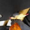
Might be hard to see with the starter in the way but if you’re way off you’ll know
 1 point
 -
Sounds like the main shift eccentric stop is out of adjustment. Check out the V11 shift improvement sticky thread and pull the selector assembly off and adjust it on the bench. Don't attempt it on the bike. ciao [docc/edit/link: V11 Shift improvement in "How To . . ." Thanks docc I'm working remote at the moment. ciao1 point
-
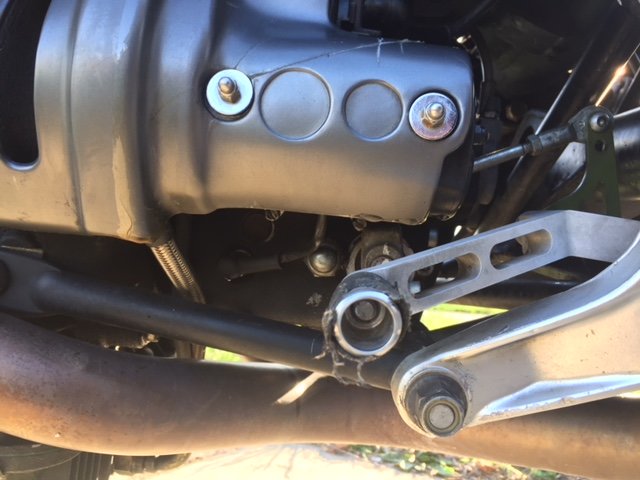
Check that your linkage is correct. I can post a pic of mine in a few minutes.1 point
-
I have nothing for you. If the pre selector is working properly.. I dunno.1 point
-
You haven’t nipped up the long allen bolt on the lever have you? It wants a wee bit o slop in it or it binds. Which is a bind.1 point
-
Just got my Genuine MotoModa P.Roper Plate today! At 110,590 miles, I figure I better get it installed before I sleep or eat again.1 point
-
https://up.craigslist.org/mcy/d/upson-2003-guzzi-rosso-corsa/6860364848.html Good luck!1 point
-
Springs are easy to tell. Measure sag, measure how much it sags without you on board and measure how much it sags with you on board. Using those three data points (fully extended, sag under just the weight of the motorcycle, and sag under the weight of you on the motorcycle) you can figure out if the springs are the right rate. Add preload (or remove preload) until the sag with you on board is around 20% - 25% of the total suspension travel. Then see if sag under just the weight of the motorcycle is around 10% - 15% of travel. If sag under just the weight of the bike is too much when sag with you on board is right your springs are too stiff. If sag under just the weight of the motorcycle is too little when sag with you on board is right your springs are too soft. That is because it takes too much preload to get the sag with you on board right if your springs are too soft. There are at least two different versions of 'zooki's. To my knowledge both are cartridge forks. Simple cartridge forks, but cartridge none the less. On the earlier version of 'zooki's like on my wifes red frame V11 the compression dampening is non-existent as built because there is too much oil bypassing the valving stack. To get it to work better we blocked one of the two bypass holes so that oil actually had to flow through the valving stack. It worked much better after that and the dampening adjuster actually did something. Before all the adjuster did was affect the last inch of travel because that is when the piston passed the bypass holes.1 point
-
You're back Chuck, not a slow trip i see Ciao You mean 2016-09-04_04-32-01 by Charles Stottlemyer, on Flickr this?1 point