

MartyNZ
-
Posts
934 -
Joined
-
Last visited
-
Days Won
42
Content Type
Profiles
Forums
Events
Gallery
Community Map
Posts posted by MartyNZ
-
-
I think that anything is better than dry assembly if the bike ever gets wet. Jointing compound, anti-seize, or grease, are all good.
-
 3
3
-
 1
1
-
-
My gearbox had small leaks and weeps because it was overfilled. Checking the level with the bike on the sidestand is bad. It must be vertical for minutes before you check that the level is in the middle of the sight glass. I can tell you that I can't do this by holding the bike up then bending down to check the level. I had leaks until I got it onto a maintenance stand.
-
2
-
1
-
-
5 hours ago, docc said:
It appears the current replacement fastener is nitrided, phosphated, or otherwise surface treated? (I realize this is not cadmium plated.)
Is this coating/treatment, perhaps, the more pointed purpose of the new fastener rather than the tensile strength change or the change of thread pitch?
Is this all about the corrosion vulnerability?
Black oxide conversion coating is good for corrosion protection, cheaper than cadmium plating, but not as good. Still, it is good enough.
-
2
-
2
-
-
1 hour ago, p6x said:
Guzzi should have computed the shear force that load bearing component would be submitted to. Usually, you send the blue prints to a specialized company and they tell you what force that component will have to sustain.
That bolt should have been manufactured to precise specifications, using a given metallurgy and maybe thermal treatment. Guzzi would have ordered a large batch to support manufacturing.
The important factor is that, the shearing strength seems inadequate for a normal usage. For such an important component, it would be probably better to have one purpose made; if we knew what the maximum shear force it has to see.
Actually we can be certain that Guzzi calculated the shear strength required correctly. If the bolt failed in shear, then we would see 2 shear planes, as the bolt is in a double shear clevis. Since the bolt usually fails under the head, or at the first thread on the shank, failure is likely caused by stress corrosion cracking or fatigue. These conditions can lead to a break at very low loads compared to simple shear.
We have to stop the rust, as a rust pit is the initiation point for a crack.
I believe that a new standard bolt assembled with anti-corrosion jointing compound will last a other 20 years.
-
1
-
1
-
-
11 hours ago, activpop said:
Are the forces the same on bolts at both ends of the rod? I have the aft one out and it was dry as a bone...no sign of lube. I wonder it that falls into the same need of upgrade as the forward one.
Yes, identical loads on each end of the reaction rod, as a single bolt forms a "pin joint". However I think that the forward end of the rod is more exposed to road spray, which explains the number of reports of the forward bolt breaking.
Assembly with an anti-corrosion jointing compound like Duralac or Mastinox will reduce rust without encouraging bolt rotation as grease would.
Since stress corrosion cracking is more likely on high tensile bolts, I believe that staying with the original spec bolt is a better idea, if you want it to last another 20 years.
-
6
-
-
I wonder if that bolt failure is related to the condition of the needle bearing in the RH side of the bevel box? 🤔
Obviously stiffness in this bearing will increase fatigue loads on the reaction rod & bolt during suspension movement.
-
3
-
-
It would be interesting to know if the heat comes from internal to the relay, or just from the engine. If engine heat is the cause of your problem, then an added baffle and reflective panel may be simpler to fit than a fan.
I'm not familiar with the 1100 Sport, but is it possible that a cooling air path past the relays is blocked by extra gear under the seat?
Something like a pack of spare relays?

Have you considered vapor lock? I fixed a similar problem on my external pump V11 by adding reflective insulation on the pump and filter.
-
2
-
-
@Chuck posted pictures of the lovely little radial 3 cyl fitted to his homebuilt here:
-
2
-
-
Docc is on to it (yet again); the two problems with the relays which have conflicting solutions; vibration in the sockets and heat dissipation.
I tried to think of a heatsink that both held the relays steady and conducted away the heat, but the relays in my bike are all different sizes, so I decided that the problem wasn't big enough to need a solution.
-
2
-
-
A curious and unnatural modification alright. But then I always wondered if relays vibrating in their sockets was the reason that the relay socket contacts became loose over the years. My bike needed the KiwiRoy fix. Maybe tape or heat shrink sleeve stops jiggling and is a good thing.
-
The guard on my oil cooler is either homemade or aftermarket. It screens out rabbits and low flying seagulls, but I cleaned out about a cupful of dirt and grit from between the cooler fins before I painted it.
I think I need a fender extender.

.thumb.jpg.e1d35af553d4da963c751e59e8dcb159.jpg)
-
2
-
 2
2
-
-
4 hours ago, cash1000 said:
Getting very frustrating putting V11 back together after gearbox work. I'm having trouble bleeding the clutch line. Any thoughts?
Have you read the comments in the "No Clutch!" post?
https://www.v11lemans.com/forums/topic/22529-no-clutch/?do=findComment&comment=259113
On 11 April 2021 @Tinknocker suggested zip-tying the clutch lever to the grip overnight. This assumes that you have got most of the air out of the system. The theory is that pressure in the system makes the air-bubbles smaller, so the bubbles can rise to places where they can escape in the next bleed attempt.
Then on 24 April @Lucky Philsuggested pushing fluid up from the slave with a syringe.
Lots of good advice there.
I have some disposable 60ml syringes that you can have.
It is good practice not to let the reservoir get close to empty. With 6mm level remaining in the reservoir, I have seen a tiny whirlpool of air bubbles sucked down into the master cylinder when the lever is released quickly.
As @gstallons suggests, having the anti-drain loop above the slave cyl bleed nipple avoids the possibility of air being sucked in as the lever is released.
-
1
-
1
-
-
On 2/21/2023 at 10:31 AM, Cold Desert Rat said:
Spine frames are two piece and welded just aft of the front airbox mount.
No big deal. Just something I was unaware of.
Carry on.
There's a plate at the weld to close the bottom of the crankcase breather chamber, inside the upper part of the spine. Condensed oil vapor returns to the sump from a port just above the weld.
Not a new idea, but it is smart, two functions for the spine.
-
1
-
3
-
-
On 2/22/2023 at 3:44 PM, docc said:
!!!!!
Ha, well spotted @ScuRoo
Both horses are fitted with a type of martingale. Also called a "tiedown" or a "head check". It's used to discourage head raising, which changes the angle of the pressure of the bit. If a horse is spooked or ornery, it might charge off with head raised, becoming dangerous and difficult to stop. Also stops the horse’s head from smacking the rider in the face. I imagine that the big knot has enough weight to warn the horse that the limit is approaching. See a pic of the Delaware police using another variation.


-
2
-
1
-
1
-
-
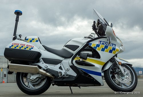
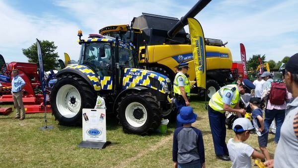
NZ cops are open to other transport options too.


-
2
-
1
-
-
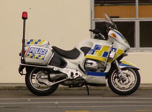
The NZ cops have several models on the road.
BMW R1200RT, Honda ST1300, Yamaha FJR1300 & MT09 Tracer.
No HDs, but they do have John Deere Gator & New Holland Tractors in police livery.
-
3
-
1
-
-
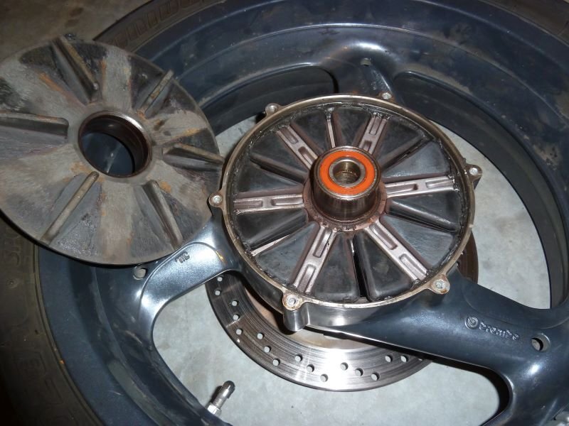
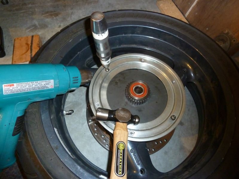
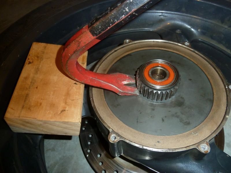
9 hours ago, Janusz said:
This crowbar surgery seems quite radical; should I expect the spline disc to be rust frozen and difficult to separate? I will be anxious not to damage it...
The spline plate can be hard to remove. The fins that engage the rubber blocks are tight, so you need a way to pry it out. A crowbar is bigger than you need, any pry bar is fine so long as you don't damage the wheel.
-
1
-
1
-
-
Then you can see 12 rubber pucks in recesses in the wheel hub. Some people grease the recesses and the non-metallic ring. I coated these with moly dry lube spray.
You can see that I fitted only half of the pucks in my bike, and they were drilled to be more squishy.
As you assemble, check that the O-ring is good, and there is wheel bearing grease on the spline plate bore.
Before you refit the wheel, put a good layer of spline grease like Staburags NBU 30 PTM on the splines at the connection to the bevel box.
-
3
-
1
-
-
6 hours ago, Janusz said:
So I've removed wheels to have new tires installed at the shop.
Should I disassemble the rear wheel and remove cush drive rubbers for tire installation and balancing or take the whole wheel to the shop?
I would like to inspect/grease etc cush drive rubbers but it seems difficult to me and the factory shop manual is not very helpful. It wants me to:
"Working on the opposite side remove the bearing and then lift the plate with gearing (do they mean spline drive??) using two screwdrivers."
Could somebody walk me through this using simple explanation please?
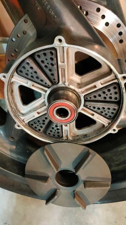
I'd say "don't disassemble the wheel & cush assembly" The tire can be changed as it is.
Also don't lose the bush that goes on the axle between the wheel and the bevel box. It's needed to get bearing preloads right.
If you're like me and can't help pulling it apart, then the following pictures may help.
The retaining plate screws are likely to be frozen. Heat and penetrating oil are your friends. How hot, you ask? Well the rear disk can be red hot without other damage, but 60°C would be safe.
Then you can lift the splined plate out.
-
2
-
1
-
-
1 hour ago, Cold Desert Rat said:
Weights of Caruso gears vs sprockets & chain.
Actual numbers! Excellent!
-
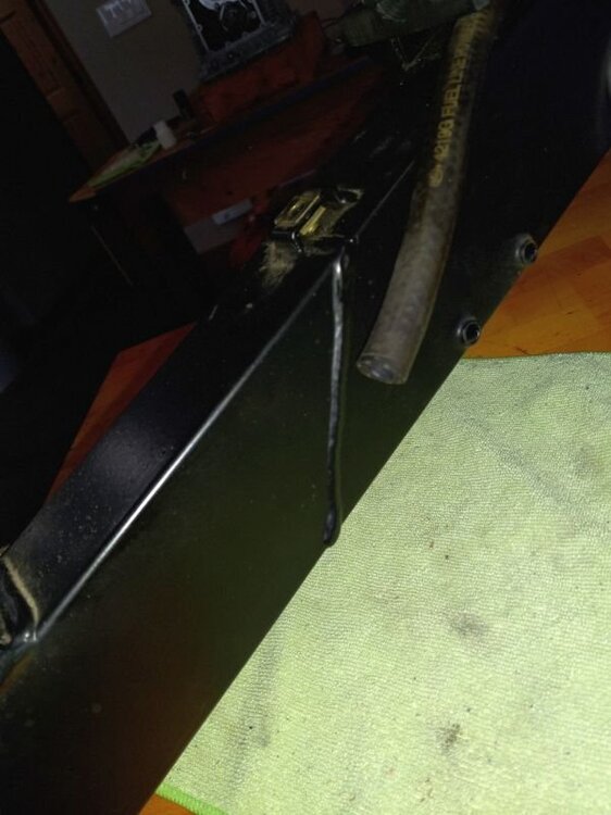
If you have sweating and stiffness in a V11 hose, I believe that you should replace it. If original, it is 20 years old now.
Make sure that you get the right specification of hose. The correct material for sub 50psi external pressure hose will not last if submerged in fuel. The correct material for hose immersion in a tank will not last outside when exposed to sun and heat. Low pressure hose for carburetors is not suitable for injection systems.
A good summary is given here, both for hose and hose clamps.
-
4
-
3
-
-
6 hours ago, andy york said:
you might try hydraulics. Use your grease gun on the zero fitting and see if you can get it to move.
If so , just remember to clean out some of the grease so you put it back together
It seems like an obvious solution, but no, there are holes in the lower end of the shaft. The holes stop excess grease from forming a hydraulic lock during normal suspension movement.
-
When I needed a replacement rear drive, I got one from Italy. It was in good order, except for freeplay that I thought was too high, been that way from new. The workshop manual did not help me, it is sparse and seems to apply to earlier models. I made pinion and crown wheel shims, then made tools (a bit crude) to allow measurements. After 14 tries, I eventually got both preload and freeplay low enough to be happy with. A slow and tedious process. Contact impression interpretation is a black art, with vague contact marks that need a strong light and a good imagination. You will never get it perfect on a worn C&W set.
The bevel box is now quiet and runs cool.
However, if your box is ok, then the only maintenance needed is oil change and spline grease.
-
2
-
-
1 hour ago, cash1000 said:
Pick up completed gearbox yesterday. Great service from Vince.
Do you have a drain bung with a magnet in it? Just in case there is still a few bits in there.
-
3
-
.jpg.3d33311f5068eea10ddfdcc859ff2439.jpg)


Fuel pressure regulator
in Technical Topics
Posted
When I had tiny leaks on my tank, I went to replace the O-rings under the flange fittings. I noticed that the screw inserts that attach the flange to the tank had pulled out a tiny bit, creating bulges in the tank plastic.
This meant that the clamping of the O-ring was reduced so allowing leaks.
Running a file across the tank insert face reduced the bulging at the inserts without touching the sealing face.