

rich888
-
Posts
98 -
Joined
-
Last visited
-
Days Won
3
Content Type
Profiles
Forums
Events
Gallery
Community Map
Everything posted by rich888
-
Not thought of that! It's not going to be easy to verify the TDC sensor operation, will probably have to datalog the pulse timing from it directly, together with the ECU RPM values.
-
And this is whats lurking under the seat...
.jpg.462acab3e04e3fd3f72edab2516f7647.jpg)
-
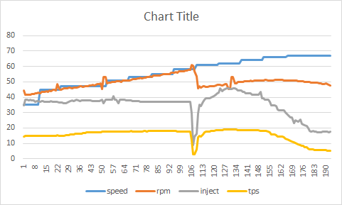
Just for interest, this is a log of a gearchange: Speed is updated every second via GPS - hence the steps! There are some disturbances in the injector timings but hard to say if they match RPM glitches. The sample rate is too slow to be sure at only 15 times per second, but I have just improved that to 30 times per second, so it may show up better... When it drys up a bit outside, I'll take another plot and keep the bike in a lower gear to keep the rpms in the 5000-6000 band for longer. I'm actually looking for the reasons for the occasional missfire / hiccup as well as the misbehaving tacho.
-
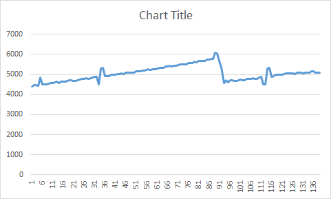
Maybe. The glitches get progressivley bigger as the RPM's go up. I assume the ECU measures RPM from the crank sensor (TDC sensor). If it is actually reading these glitches, I would expect it to cause glitches in fueling too... I would assume that the TDC sensor provides pulses, so don't know how it could trigger early and then late? Mabe the ECU is doing some averaging and getting it wrong!??
-
Using my homebrew datalogger, I noticed that the RPM value reported by the ECU also has glitches in: Not sure if this helps explain the dodgy Tacho Gauge or is some other issue?
-
£450 to alter a few hex codes in the bin file? Good money for someone!
-
Postage from the USA to UK? WTF?
rich888 posted a topic in Special place for banter and conversation
I wanted to buy some wideband lambda controller boards from wide-band.com. They are cheap at only $20 each. "Shipping" for a board smaller than a credit card? $93.... Can't stuff just be posted in US Mail? I can buy stuff from China for a £ or two including 'shipping' and while it may take a couple of weeks, it always gets here... -
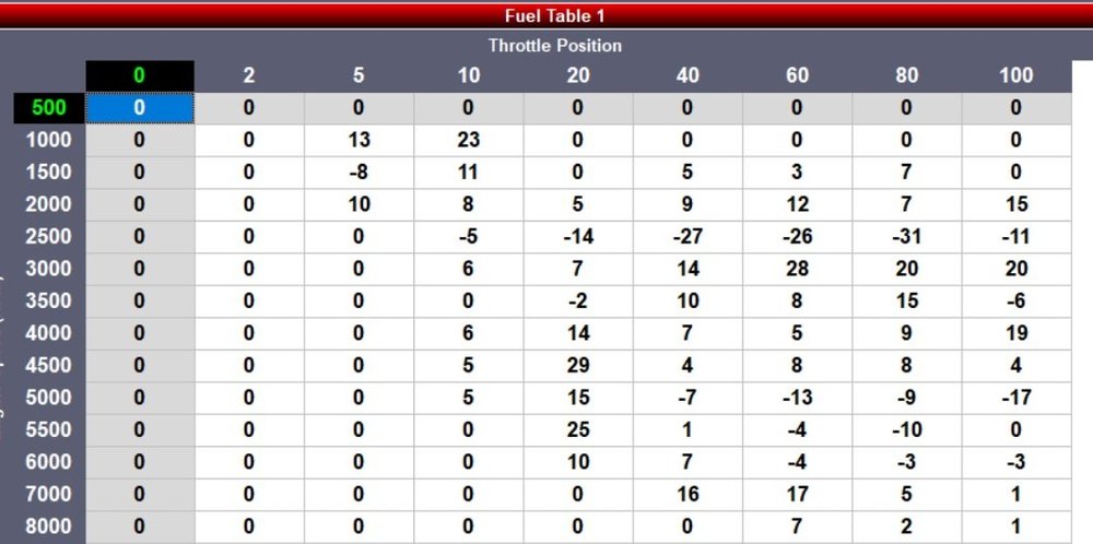
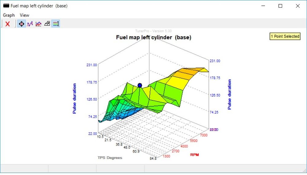
I actually have a PC3 too. It has this map in (which the previous owner paid a lot of money for!)
-
Looking at the stock fuel map for a 2001 V11, it has some odd peaks and troughs in: Anyone know why this is? For example at 2000 rpm tps 48, is a peak of 193, which drops off at higher and lower rpms and higher and lower tps. There is also a low fuelling trough at 4000 rpm at wider TPS values.
-
Got the GPS module today. Just amazing that these things are so small and cheap... Imagine showing one to John Harrison... Anyway, thanks to Beard over on Guzzi-Forum.De of GuzziDiag fame, for helping with a few pointers regarding the ECU and the interface. The trick will be packaging it so that it's descrete and readable.
-
I am using a very small OLED display which is big enough for 2 digital readouts and 1 bar graph or dial. These can be any of the data items available from the ECU. These screens are very cheap and very clear even though they are less than an inch across. Could have 2 or 3 of these mounted together... I will also test a small colour TFT LCD screen which is 2.4" and has a touch screen. It should allow maybe 6 things to be displayed. Just need to see which works best in sunlight. Also have a tiny GPS to add, in order to get MPH and then work out current gear position.
-
Birds nest:
.thumb.jpg.34cfbea987a51bf4241c876123e6391e.jpg)
-
Here's a vid showing how far out my tacho is from my homebrew all electronic tacho: https://youtu.be/XXqWtwz_LTQ Eventually hope to replace the analog tacho with a digital version that will have serveral readouts on...
-
Great thanks. I was looking at TE interconnect superseal 1.0 I have a spare ECU that I want to plug into to develop my scangauge, instead of balancing everything on the bike the garage!
-
Video of it here: https://youtu.be/XXqWtwz_LTQ You can see how far out the analog tacho is!
-
Had a play at this today: This is obviously a birds nest prototype but it works fine!
.thumb.jpg.331a3907bb6f6a2d049bb0c6603bd126.jpg)
-
hello JB, I did clean a lot of black sticky stuff off the throat taking extra care around the place where the butterfly seals. Awkward without taking the TB off, but possible with a mirror and Q-tips. Initially the butterfly was sticky. You could feel it once disconnected. As the valve is spring loaded, it can snap back, if you let it. More realistically, if you let it gently close, it does seat at more of less the same place. Obviously this is a position it will never normally be in due to the stop screws, so the butterfly is seating onto somewhere 'new'.
-
Only 8 bit! (it's a 68HC11 isn't it?) So 19mV steps with some non-linearity thrown in! Does the throttle position reported on GuzziDiag relate directly to the raw TPS reading or is there some rounding?
-
Yes could be that. I cannot feel any play, but the TPS is very sensitive. It picks up tiny movements. The bike has 30,000 miles on the clock.
-
Anyone know the original manufacturer of the ECU plug, harness side? IAW15M ECU. I assume Aptiv/Delphi of some type?
-
OK Thanks Meinolf! I thought I was going mad! I will using both stop screws for idle and the white knob for 3k, which should tune out backlash/slack in the linkages... One thing I did notice while setting TPS, the fully closed position with no throttle stop is quite variable. For example, if you let the trottle close gently, the TPS may read 180mV. If you let the trottle snap shut, the TPS may read 150mV. Trying to get consistant 157mV is impossible as the closed position is variable depending on how much force closes it. I thought this may be due to dirt and soot inside the TB so I cleaned it. The bore and the edges of the butterfly. It is still showing some inconsistancy.
-
Hello again, I understand what Meinolf is saying. So to clarify, (and ignoring GuzziMoto as instructed ) You set idle synch with the connecting rod disconnected. Using the throttle stop screws ONLY. You then adjust and connect the rod ensuring that both TB's are still on their stops. Then set the 3k balance with the adjuster knob. What I do not understand is if the two TB's are at rest on their stops, the rod is set to allow this and then rod length is adjusted to balance at 3k, one of the TB's must move off it's stop when returned to the idle position. Am I being thick? I am I missing a neuance of the connecting rod?
-
I've been looking around at TB balancing/synching. There appears to be a few schools of thought about setting idle balance. I was advised by Meinolf, after loading his bin file, that both air bleeds should be closed and that I should idle synch using both throttle stops. This is obviously counter to most of the posts that say only use one throttle stop to set idle speed, or some that say to use the air bleed screws. I am thinking that, after setting TPS, closing both air bleeds, I leave the throttle link bar disconnected and set the idle balance with just the throttle stops. Then reconnect the throttle link bar making sure it's adjusted to keep the idle in balance. Now set 3k rpm balance with the white knob. I can't quite see how that won't change the idle balance? Am I missing something?
-
Yes, I have only set the left throttle stop as described in the tune up posts. Is there a detailed proceedure for synching both throttle stops I can read? I have a dual vaccuum gauge and gear to read TPS etc.
-
Interesting! There's not much software in these ECU's !!!! Does your bin file have any software changes or is it purely data table changes?


.jpg.6c86086b99296e85f81f0da4413caebf.jpg)
.jpg.490fdaa104c637a3e1abe6c032f507f9.jpg)