Meinolf
-
Posts
160 -
Joined
-
Last visited
-
Days Won
16
Content Type
Profiles
Forums
Events
Gallery
Community Map
Everything posted by Meinolf
-
Hi, the point is the following. The ECU uses two tables with fuel injection values, left (main) and right (delta) cylinder. The tables are indexed by throttle opening (TPS value) and rpm. The TPS is attached to the right (delta) throttle. The challenge is to synchronize both throttle valves so that they are using the same TPS breakpoints. This is essential a small throttle openings, as the TPS breakpoints differ initially only very slightly. At idle the springs are pressing the butterfly valves against the stop screws. Due to the numerous joints there's some play, which is overcome when opening the throttle. So, two different states. Pressing at idle, drawing when opening the throttle. My description is a pre-requisite when using my BIN, as the fuel values were arrived at logging lambda data based on it. Cheers Meinolf
-
Hi, connect Guzzidiag, select graphical display and watch if the curve is smooth when opening/closing the throttle. Beware that there's a change in the gradient at 30°, it get's flatter when opening, due to the characteristics of this TPS's curve formula. Cheers Meinolf
-
Hi, setting the TPS to it's proper start position (which is 157mV with all connections removed) can only be done with a physical adjustment and a voltmeter - not Guzzidiag or any other software. Cheers Meinolf
-
Hi, I've spoken to Paul's daughter some minutes ago. She asked me to convey thanks to all who expressed their concern. Paul's condition is still unchanged, but not worse. Cheers Meinolf
-
Hi, Yes, that's what it boils down to. Well, you don't need special vernier sprockets. Re-boring the index hole in the sprocket with the desired offset is the way I do it. I don't understand the question. What do you mean by effective valve clearence? Cheers Meinolf
-
Hi, I don't want to niggle, but make sure no wrong conclusions are drawn from above. Using different valve play values should be done only if all relevant factors are known. Simply increasing valve play to garner the benefits of better VE without having a measured the camshaft and valve lift would be a dangerous game. Skipping the ramp up portion entirely is comparable to hammering the valve and all involved components instead of having them smoothly brought up to speed. And, as the total valve lift will happen during a shorter time, the acceleration would increase. Which might lead to valves simply being torn apart or overshooting because the springs can't cope with the increased inertial moment. Just sayin` Meinolf
-
Hi, sure, a ridiculuous amount would be nonsense and result, amongst other things, in little gas flow. Keep in mind my remarks "...Disregarding all other factors..." and "...Increasing it, within reason, ..". The ultimate goal is get as much air mass into the combustion chamber at the time it's needed and can be utilized. This is expressed as volumetric efficiency. If you have a pump (cylinder/piston) with 1l volume, the largest air volume which can be brought into the pump is 1l, which is a volumetric efficiency of 1. Now consider a combustion engine to be a flow machine. Before opening the valves the air is waiting to get into the combustion chamber. When the valves are opened it can stream into the combustion chamber. The faster the valve opens the faster it can get into the chamber. The speed of valve opening is determined by gradient of the camshaft. By increasing the valve play the controlled (and slow) ramp-up is partly skipped and the opening time (fully closed to fully opened) is shortened, the valve is actuated faster because it's already at a high gradient part of the camshaft. Hence, the air flow will increase. Decreasing the valve play would result in an earlier opening of the valves, but only a slight gap one. The air waiting to get into the combustion chamber is trickling instead of charging, overall volumetric efficiency will decrease. Hence, less air mass arrives in the combustion chamber at the end of the cycle. Having said this, this is a rather theoretical discussion because other factors, such as max. acceleration/deceleration, spring rate, weight of the moving parts of the valve train, surface pressure and so on need to be taken into account. Cheers Meinolf
-
Hi Kelly, valve play and timing have no connection. I've never measured AFR with a mistral crossover and oval exhaust. My setup is standard crossover and TI exhaust (which flows significantly better than the stock exhaust, but is quite loud) Again using a picture from Motoguzznix's file for visualization, the timing is dependent on the camshaft. It's best practice to adjust the point at which the intake and exhaust valve have the same lift to 2-3° before TDC and not at TDC. Or even behind, which is the reality in Guzzi engines after some time because the chain has worn a bit. The main issue with the V11 valve train are the guides, you will typical see a much larger play than factory specs after some time. So, changing the valve play versus the 0.25mm I've used will impact AFR and not timing or wear and tear. Disregarding all other factors, decreasing the play would reduce the airflow, which would lead to a richer mixture than I intended. Increasing it, within reason, would slightly improve airflow and lead to a leaner mixture. But as I wrote previously, the V11 camshaft is a good one, stay with 0.25mm. Cheers Meinolf
-
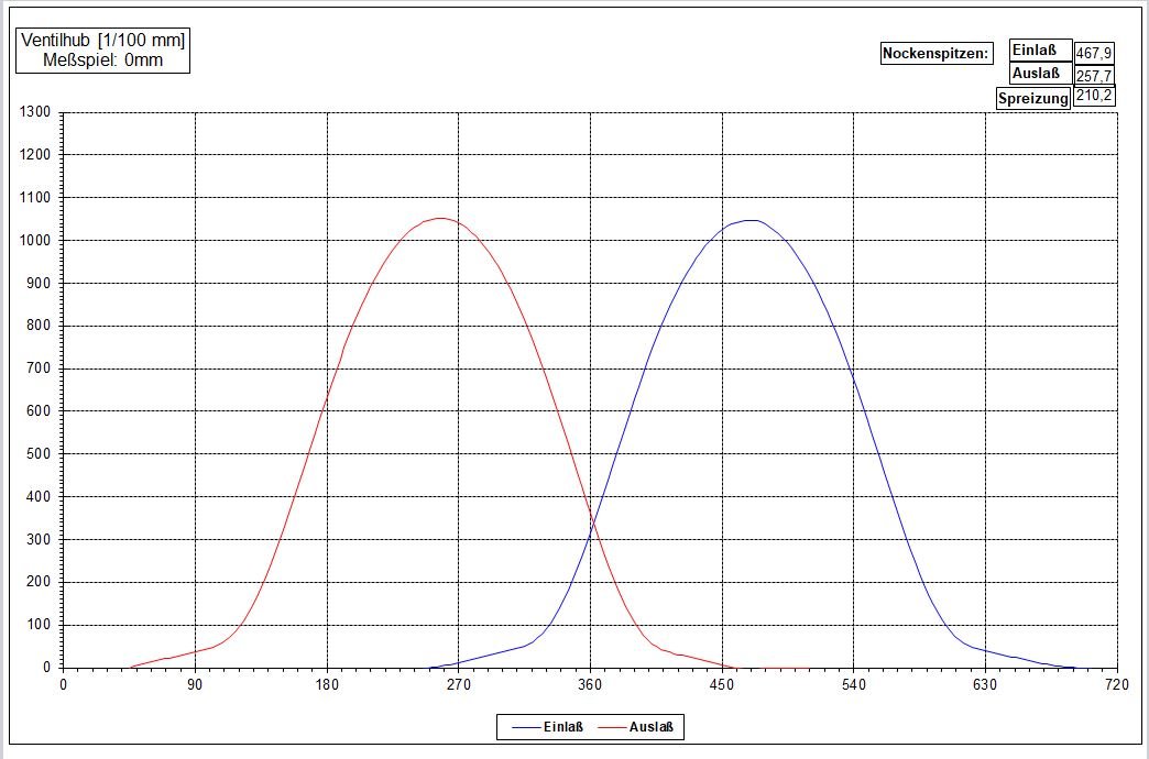
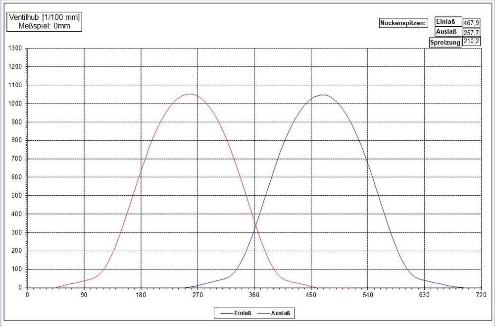
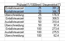
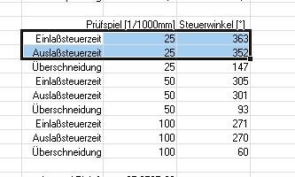
Hi, I'm being quoted as recommending a valve play of 0,3mm or larger for both exhaust and intake valves on the V11. I can't recall recommending this for the V11. The V11 camshaft is very good and the ramps are not overly long. Using 0.25/0.25mm is my recommendation. The old Tonti camshafts, on the other hand, are best served with a valve play of 0.35/0.35mm. The have very long ramps, using the factory recommendation of 0.25/20mm leads to a opening angle of >400°, the valves are slightly (1-2/100mm) open over a wide range during ramp up. The effects are decreased valve cooling time, loss of mean pressure and cylinder fillling. The two pictures (Copyright Motoguzznix) show the effect for the 2 camshaft types. Cheers Meinolf
-
Hi, I assume that by "original speedometer" you mean a dashboard. Which is talking to the ECU via CANBus, the immobilizer function being one of the bits transmitted over the bus. The 15M/RC don't use CANBus, the speedometer is just triggered by a pulse. Replacing it does not inhibit the starting. Cheers Meinolf
-
Hi, on 2nd thought your comment deserves a more detailed reply. The name cold start is not well chosen. Start-up fits better. The reason why the start-up function is needed and why it's temperature and to a lesser degree revs since start dependent is the following. After pressing the starter button the injectors begin injecting fuel, the nozzle and the fuel jet are pointing towards the opposite side of the intake pipe . At that time there's almost no air flow and a very low air speed moving through the intake, hence the first fuel shots are creating a fuel puddle on the opposite surface of the intake tract. A surplus of fuel, which is caused by the trim values, during that period ensures that enough fuel gets into the combustion chamber to achieve a ignitable mixture. This effect is engine and air speed dependent, so a temporary enrichment for some revs is needed at any engine temperature. Once the engine is turning over at a higher speed, the resulting higher air speed moves more of the injected fuel into the combustion chamber. And the increasing temperature of the engine increases the evaporation of the fuel, again resulting in more fuel getting into the combustion chamber. My current conclusion, based on the measurements, is that the critical values in the start-up table are those used during the first 10-50 revs. Once the engine is running on its own the start-up table values can be replaced by fuel engine temp trim table. Cheers Meinolf
-
Hi, It might not be that cold, but the breakpoints go up to 125C. So yes, 65C. Cheers Meinolf
-
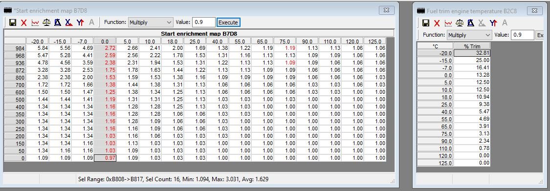
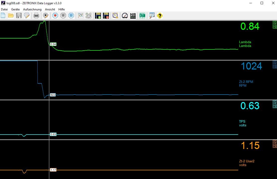
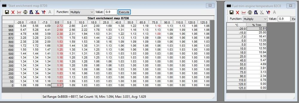
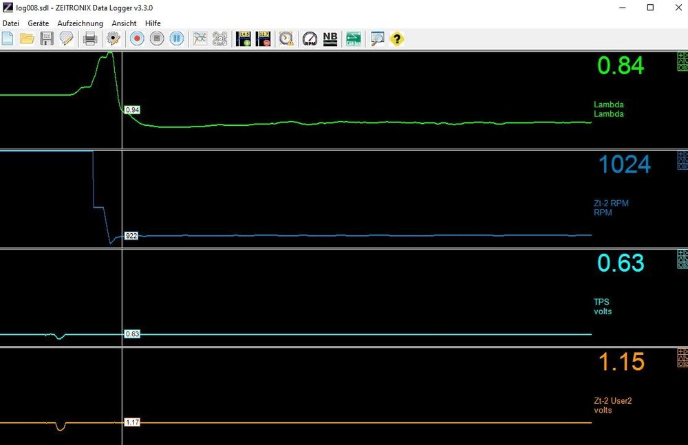
Hi, as chance goes I've been revisiting the engine temperature related trim functions on the Jackal, since the current temperature are below 0°C and the respective engine temp breakpoints could be reached. The Jackal is also using the 15M, so it's seems relevant to this thread. The start enrichment map and the fuel trim engine temp map were already changed several years ago on the V11 and Jackal, but at that time the logging equipment was from Innovate. Unreliable product and poor support led me to changing to the Zeitronix ZT2s. Those we hooked up to the Norge, but I got several more ZTs and mounted them on the Jackal. The basic measuring procedure was already planned last year. The ZTs have two 0-5V inputs. But, both are being used during the normal logging. The first one is attached to the TPS, as the standard input only provides for measuring TPS as a integer %-value. Which is not good enough in the lower third of the TPS range, %-values overlap the degree values. The 2nd input gets the lambda signal measured by the 2nd ZT2. So the 2nd ZT2 was temporarily disconnected and the engine temperature sensor connected instead. As mentioned above the engine temp related fuel trims are taken care of by two mechanism. The first is the start enrichment map, indexed by engine temperature and number of revolutions since ignition on. I've changed the standard 2000 revs in my BINs to 1000 a long time ago to minimize the interference during the normal logging. The index is to be understood working in reverse, to the first step is 1000-984 = 16 revolutions. And so forth, until the total number of revolutions, specified in a scalar, has passed. The fuel trim engine temp map is a 1D, only indexed by engine temperature. Both functions overlap, so a trim by this table is factored together with the current start enrichment factor. One of the pictures shows both tables. The 2nd picture shows the log of a cold start at ~65°C, which is the voltage coming from the sensor at that temperature. First line is lambda, then rpm, then TPS and then the voltage from the engine temp sensor. As preparation a look-up table voltage vs temperature needed to be created. This was done by running the ZDL software and GuzziDiag at the same time and noting down the corresponding values. The measuring procedure is starting the engine with and logging the data. The inital data, while the rev countdown is still running, is used to check and correct the trim values in the start enrichment map, then shutting the engine down and repeating the procedure at every engine temp breakpoint. Which takes 20-30 tries, as the engine temperature keeps rising by 5-8°C after the engine was shut off. Longer runs are used to get lamba values across the temperature range without the start enrichment influence. These are used to check and correct the fuel trim engine temperature table. And this opportunity is also used to re-evaluate the main fuel value at the lowest rpm/lowest TPS breakpoint, which I don't normally reach while driving. My idle speed is higher than that, but it is nicely reached during cold starts. It will take another day or so, but the first results are very good. The original values in the start enrichment map are much to rich, a lambda of <0.7, down to 0.6, is standard. Which is puzzling, as this is below the point at which the mixture will ignite at all. Good engineering by Guzzi, maybe. The corrections already made brought lambda in the range of 0.84-0.92, which I will try to equalize as good as possible. The fuel trim values are more or less finished also, at least in the range from 0° to 90°C. The higher values will be done while road logging, Beard kindly added a temperature filter function to the database program he wrote to analyze the massive data volume created by the ZT2, close to a million data points in one hour. Cheers Meinolf
-
Hi, you called me, the genie comes out of the bottle. Gentlemen, let me set things straight. There's in fact a warm-up function which in all Marelli 15xx BINs I've come across runs for 2000 engine revolutions after start, regardless of bike manufacturer. Neither the warm-up table nor the other trim tables mentioned below are hard-wired. They can be easily changed. I suggest one should know what one is doing before making any changes, though. The factor applied to the value which eventually will determine the injector opening time is in a 2D table. The x-axis is revolutions since start (every start), the 2nd axis is engine temperature. Search for warm-up table and you will find pictures of the table. Or use Tunerpro and load a BIN. The typical warm-up table has a factor of ~ 600% at -18°C engine temperature for 2 revolutions after start, the value tapers off with increasing revolutions. At higher engine temperatures the values are lower and taper off more quickly. Either way the warm-up function ends once the revs since start, every start, have passed. But.... There are two further temperature trim tables, also factors, which are part of the fuel calculation. One is a 1D engine temperature-indexed table, the other one a 1D air temperature-indexed table. Plus another other trim tables for air pressure and acceleration/deceleration. So the fuel calculation looks roughly like this. Fuel map value x factor engine temp x factor air temp x factor warm-up x factor air pressure x .... = final fuel value -> converted into a injector pulse width measured against end of pulse in relation to crankshaft as determined in the fuel phase table. See, no magic involved, very basic stuff. I've found that, as with many other trim tables, the warm-up and engine temp trim tables in Guzzi (and all others) BINs are not as dictated by the laws of physics and the circumstances of the engines (V11 and California) I've logged. Accordingly the warm-up and trim tables in my BINs are corrected. I've stopped my work on the V11 BIN 2 years ago and moved on to the Jackal and currently the 5AM ECU used in the Guzzi CARC models, the Aprilia Mana and many Ducatis and Morinis. So the more recent posts and results of the reverse engineering can be found here: https://wildguzzi.com/forum/index.php?topic=93758.0 or https://www.ducati.ms/threads/5am-bin-analysis.718031/ or https://www.apriliaforum.com/forums/showthread.php?336210-ECU-tuning-Looking-for-information Any further questions? No, then back into the bottle Cheers Meinolf
-
Yes, that's correct. The active word being "most" Cheers Meinolf
-
Hi, Higher numbers are newer versions. Cheers Meinolf
-
Hi, it's version 93_6, dated 2017.08.31. Cheers Meinolf
-
Hi, I still get frequent requests for the latest V11 BIN. During the last 2 years my activities have moved on to other bikes, Guzzi Jackal, Norge 1200 2V, Aprilia Mana GT and Aprilia RST 1000 Futurua. So I didn't have the time and inclination to do further work on the V11 BIN. This will likely change, as I plan do some work on my V11 (suspension, cylinder head porting, valve & valve guides, valve timing, ...) during this winter. Also the experience gained since scrapping the unreliable and error prone Innovate LM2s and moving on to the Zeitronix ZT-2s plus a enhanced set of software tools (programmed by Beard) have led to better data logging and analysis quality. If I get usable results for the V11, I'll share them with you. In the meantime the V11 BIN can be downloaded here: https://drive.google.com/open?id=1e7MMuO6vrUZGFfmkCtL3zsW1qeS6uDgY My recommendation for the basic setup, which is tightly linked to the BIN, is: - CO trim set to 0 (using GuzziDiag or directly changing the EEPROM value) - Both bypass screws completely closed (I could have built the BIN and fuel values with opened screws, but this would have introduced an additional error source. My half turn open is likely different from your half turn open. Completely closed is rather unequivocal in comparison). - TPS baseline set to 157mV (The 150mV found in the service manual and many other places in the internet are wrong, the Marelli or Guzzi engineers had rounding errors in their calc. 7mV are not much, but why not do it correctly if setting it anyways) - Idle sync using the two throttle stop screws (I've explained the reason several times already. The play in the diverse parts of the throttle opening and the spring push (throttle closed) versus cable pull (throttle open) operation makes this the only way to get a sync at idle as perfect as possible. While my V11 is mostly stock, I introduced several changes. One is the bell shaped opening of the intake snorkels, another one is the rework of the throttle butterfly valves and their shafts. These, and the TI cans I'm using, have increased airflow thru the engine. Meaning that bikes which do not have a similar airflow or, for example, have the airbox removed (very bad decision), will run richer than required. If you believe this is the case, just reduce the left cylinder fuel values in small steps until you are satisfied. DO NOT change the right cylinder fuel values or you will loose the biggest advantage of the BIN, which is synchronized Lambda/AFR values across the cylinders. Cheers Meinolf
-
Hi, Beard's PayPal name is guzzidiag@gmail.com. The Guzzidiag software has a clickable link to PayPal using this email address. Cheers Meinolf
-
Hi Tom, the pleasure was mine. Cheers Meinolf
-
Hi Dave, I don't know if the hardware of the ECUs used is exactly the same, the additional identifier (16Mxxx) on the ECU label would help in answering this. The code used in the Duc BINs is similar or identical (given the hardware of the bike is the same) regardless of the bike's make. Marelli uses a code library approach, many code sections can be found in all ECUs (P8, 16M, 15M, 5AM and even 7SM, though this one uses an inline coding technique). Cheers Meinolf
-
Hi, why would one continue to use a PC after direct editing of fuel maps became possible escapes me. The PC is a wart on top of the ECU and the axis values don't match the ones used in the BIN at all, with all the detrimental effects resulting thereof. Which could be rectified, the Dynojet Power Core software allows changing the TPS % values and adding additional columns. They could be brought much closer to the degree values, at least on the 15M, where the low degree values can be represented with % values to a sufficiently good enough approximation. And Dynojet, upon request, also changes the rpm values and columns. Cheers Meinolf
-
Hi, first and foremost the the peaks and troughs are a reflection of the volumetric efficiency of the engine. Air mass going into the combustion chamber does not increase linearly with rpm or TPS opening. Cheers Meinolf
-
Hi, yes, the MCU is a 68HC11. All ECUs (Marelli 15M/59M/5AM and Sagem 1000) whose code I've dissassembled use raw look-up tables for the digitalized input and a conversion look-up table. The raw values are only used for out-of-bounds checks, most of the code uses the converted values. Which makes sense, as most raw values are reversed - low raw values equivalent to high converted values - and using a look-up table saves some code and computing time to reverse the data. And look-up tables make it easier to adapt to new sensors, be it NTC, potentiometer or whatever. Cheers Meinolf
-
Hi, and just to close this off. The 157mV I recommend as TPS base setting stems from the TPS ADC look-up table in the BIN. Guzzi, or more likely Marelli, made a stupid mistake in this table because a wrong rounding was used. The ADC in the 15M/RC is a 8bit device, translating the (analog) voltage coming from the TPS into 256 digital steps. 5V divided by 256 equals 0,01953V. The difference between 150mV (factory recommended value) and 157mV is quite small, in fact if falls under the graininess of the ADC function (look this up in the web if interested), but why use a wrong value if the correct one is known. Cheap blueprinting, as it is. Cheers Meinolf