Camn
-
Posts
154 -
Joined
-
Last visited
-
Days Won
4
Content Type
Profiles
Forums
Events
Gallery
Community Map
Everything posted by Camn
-
I'm sure the Germans don't need a sample. Only I do not know if they are interested in making only few small parts.
-
Preemptive Shift Return Spring and Pawl Arm Replacement
Camn replied to sp838's topic in Technical Topics
OK. I understood that there is only one eccentric, which is the "Nr.9", only the pictures (Harpers/Guzzimanual) were drawn differently. Guzzimanual as seen from inside (eccentric on the left), Harpers as seen from outside (eccentric on the right). -
Download the Workshop Manual and see Part O, side 8: “2 Transmission shaft” (forget the text about replacing the whole shaft). I have been so stupid that I have put the shaft together so that the paint marks were aligned – which was totally wrong. There were smaller markings (3 dots hammered in) which were the right ones that had to be aligned. The main thing is, U-joints, which must locate on the right position to each other. There is a picture on the manual, page 9. http://www.thisoldtractor.com/moto_guzzi_misc_workshop_manuals___shop_manuals___service_manuals.html
-
http://www.seby-poly.de/dow_e.html On Wildguzzi forum there was a word on 28.8.2013 “Stucchi has gone bust”. This Company (link) has made special parts for italian motorbikes. If there would be a group order and possibility for a longe delivery time I guess it could work?
-
Preemptive Shift Return Spring and Pawl Arm Replacement
Camn replied to sp838's topic in Technical Topics
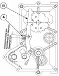
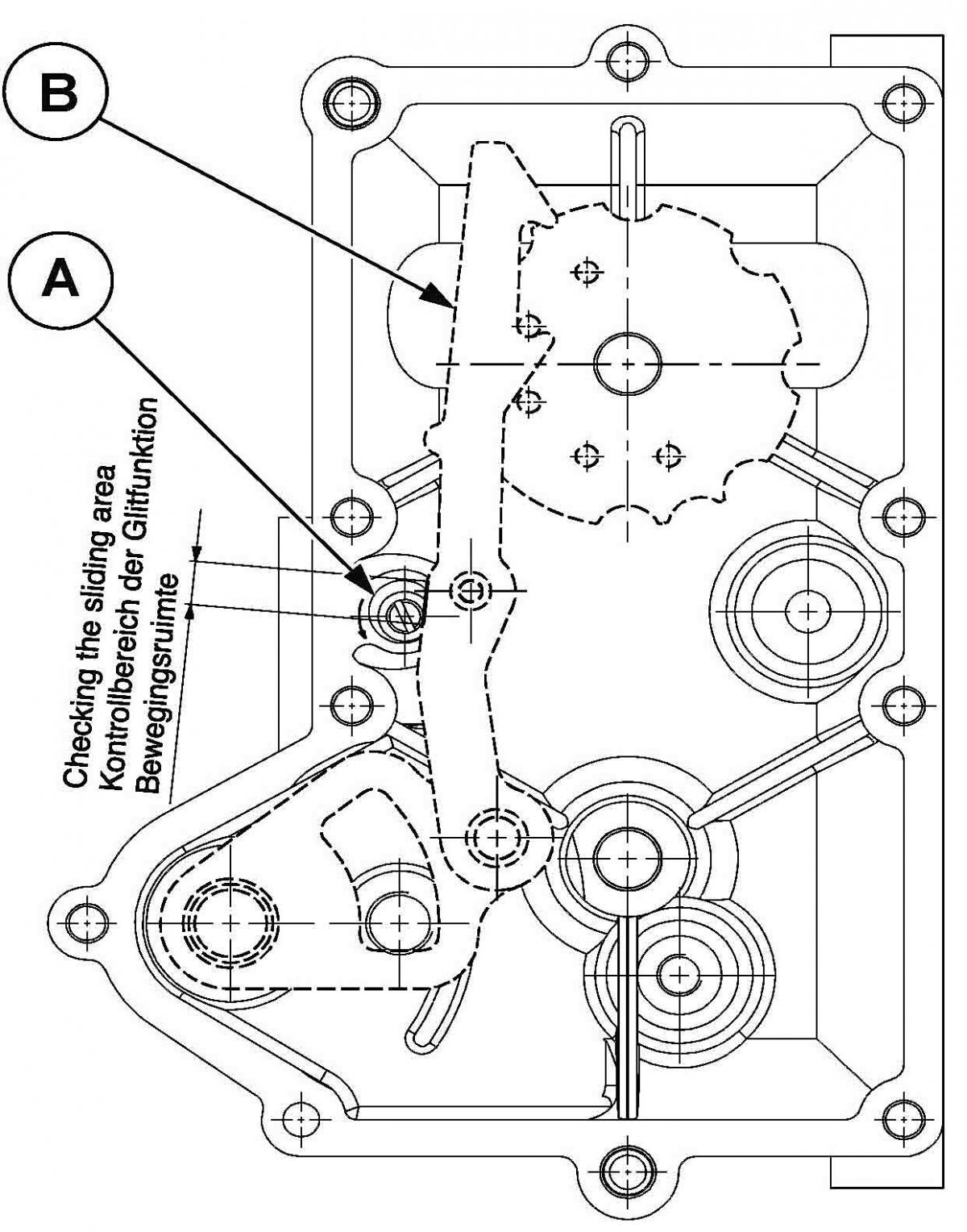
I think this is explained also in the Workshop Manual, later "update" addition? " 36 GEARBOX Contrary to the previous model, the gearbox is equipped with a special adjusting eccentric “A” used to adjust gear selector hook “B” position. Gear selection will thus be improved and more accurate. To check wheels correct operation, adjust hook position on right wheel; Position hook “B” upwards and then turn eccentric “A” counter-clockwise with a screwdriver to move it towards hook “B’; Check that the area between eccentric “A” and hook “B” – marked on the drawing – is free. "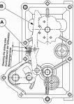
- 48 replies
-
- 1
-

-
- false neutrals
- gearbox
- (and 2 more)
-
Congratulations. A Guzzi dealer can even look up (Piaggio database) with the VIN the exact day, when your Scura was produced in Madello del Lario. Clutch - when it now is possible, I would enjoy the original lightweight (single plate) clutch. Mine was done after 30.000 km. The mechanic said that any additional start could have been fatal… A Scura should have the “single disc feel” (revs up happily, clutch lever is light, sound is different). If it is not possible to change the single disc clutch to a new one (parts not expensive) always latest after each 30.000 km, then it means modification to the standard double disc clutch (parts expensive). I have understood that there really aren’t possibilities to reduce the weight of a double disc clutch so much, that the “feel” would change (revs up a bit differently, clutch lever is hard to pull, sound is “normal Guzzi clutch”). Springs - I was told that the original springs at front are 08701-90 (9 N/mm). I have now the 09701-10 (10 N/mm) sprigs installed (strongest available), and I use 8 mm (8 turns out of 15) spring preload. Rear shock has the original spring 1091-26/85 (85 N/mm) which is OK for me when I ride alone with 16,5 mm spring preload. I weigh with gear 210 lb.
-
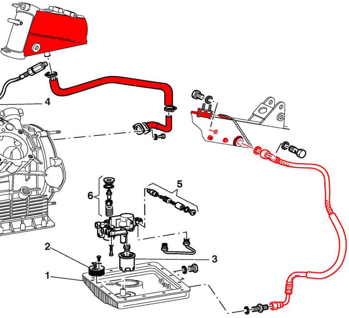
V11 breathing / oil return.
-
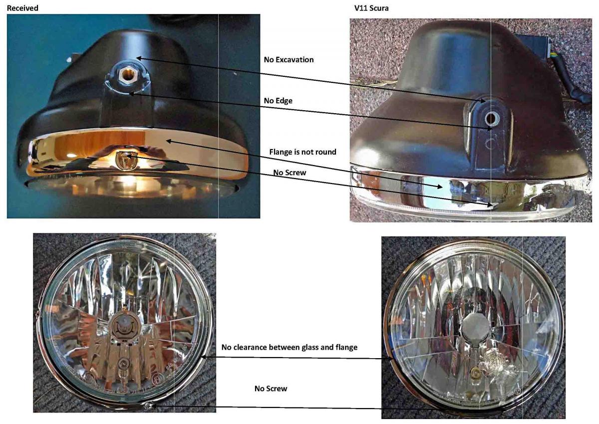
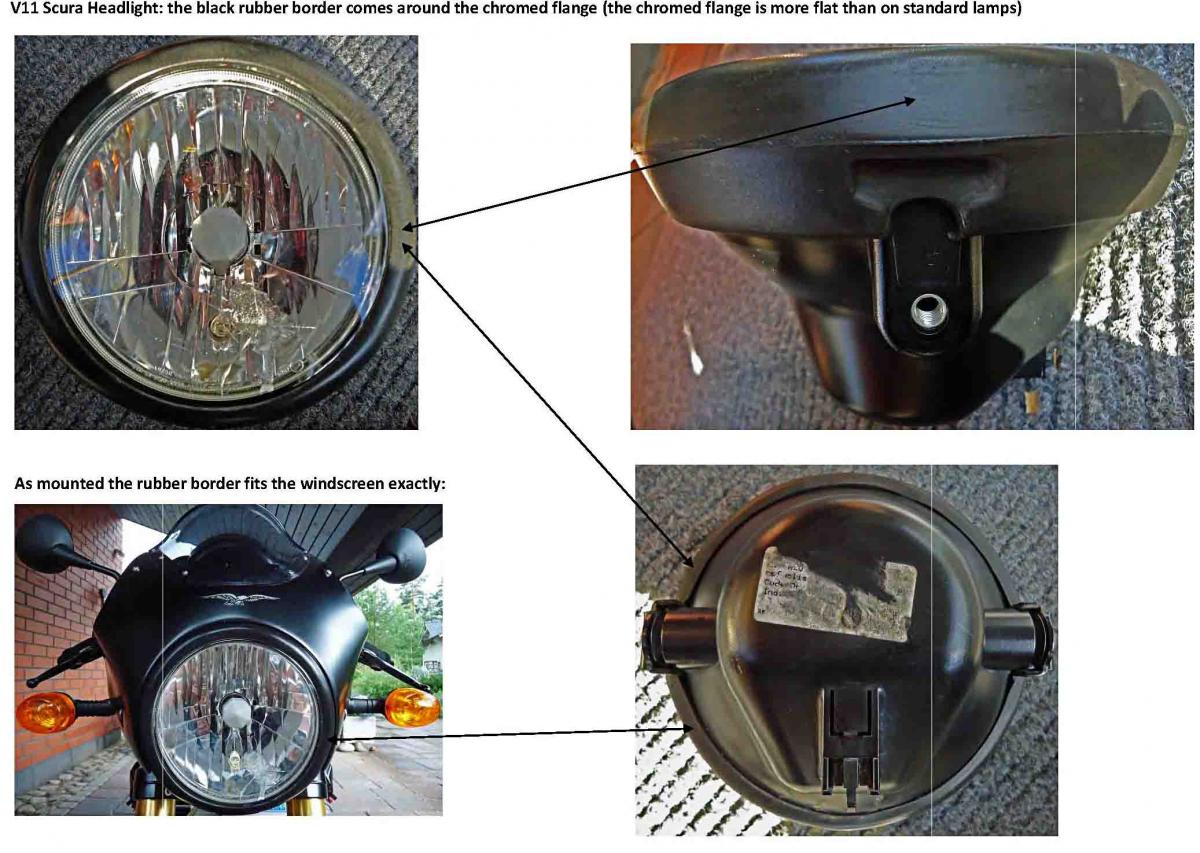
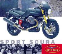
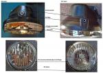
Until 2003 “long nose” models (Café, Coppa, Scura R, Ballabio) the spare part books also confirms this. Sport Naked = metallic, chrome ring fixed with a screw. Scura and LeMans models = plastic, rubber ring around the chrome ring. Surprisingly USA models have different spare part numbers. From 2003 on the headlight looks like a metallic one, although there is the small fairing. Also the Rosso Mandello had a metallic one, I think? Spare part book 2001-2002 (Sport Naked, -Scura, LeMans, -Tenni) Headlight Sport Naked: GU03740430 Headlight Scura, LeMans, LeMans Tenni EU: GU01740560 Headlight Scura, LeMans, LeMans Tenni USA: GU01740567 Spare part book 2003 (Sport Naked, LeMans, Rosso Corsa) Headlight Sport Naked: 03740430 Headlight LeMans/Rosso Corsa EU: 01740460 Headlight Lemans/Rosso Corsa USA: 01740467 Spare part book 2003-2005 (Cafe, Coppa, Scura R, Ballabio) Headlight EU/USA: GU32740510.
-
The second picture.
-
”Luxor 6422 H4 W5W” reads on the glass and on the outer side of the plastic reflector. I ordered the cheap metallic one and had to send it back. I could find the plastic one only as original spare part ,which is very expensive. Then I bought one used from a LeMans guy and another used form a Scura guy – these were identical. And made “the best possible compilation” out of three.
-
http://www.ohlins.com/Products/MountingInstructions/MI_MG126.pdf "Mounting instructions Öhlins shock absorber kit MG 126 for Moto Guzzi V11 sport"
-
If you type your VIN here, doesn't it say which model it originally has been? http://static.piaggio.com/recall/form-piaggio_en.html
-
Right...
-
www.servicemotoguzzi.com: GEAR CHANGE PAWL SPRING Subject: broken gear change pawl spring, Model: V11 Problem: broken gear change pawl spring Solution: In case of breakage of the pawl spring in vehicles with frame numbers before KT111435 - KS112350, the pawl should be changed (when asking for the spare part, you automatically receive the pawl updated version). The change consists in the reduction of the diameter on which the spring rests from 16 mm to 15 mm.
-
The owner of the broken reaction rod wrote that the bolt was M8. The bolts on the original Guzzi reaction rod were at first M10x59 (1,25 thread) and later M10x55 (1,5 thread), which is still available as spare part. Although the original reaction bar has rubber bushings; still there have been reports of broken bolts on this also. It could be, that on this ("M8") case the bolt had some kind of fault originally? I read that a M8 bolt has an inner thread diameter of 6,9 mm, and area of 38 sq mm. The pulls and bends when driving could be too much? PS. "Pre fuel injuction" Daytona and Sport1100 had also a similar structure on the reaction bar like the broken one had.
-
http://www.v11sport.de/forum/viewtopic.php?f=10&t=5706 (See the photos on the thread above), what can happen if there are "thin & lightweight" parts in the system. For normal safe street use with no extra checks with the reaction rod, I would not use any other than the original part.
-
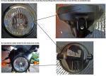
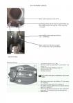
I'm not an expert on this, but I just happened to have my back wheel off the other day (new tyre + brake disc): Picture 1: The spacer (bushing) is the part #18. First slide the axle (part #16) through the gearbox and then slide the bushing over the axle untill the very end. Picture 2: When on the axle, the bushing lies inside the part #29 (grooved for the opposite part on the wheel). PS. Picture 2: When the wheel and axle is off, take spacer/cover #33 out and grease well the needle bearing #31. I have read that many here in Europe do not want to tighten the nut (#17) for the axle to the given 120 Nm because of the bearings.
-
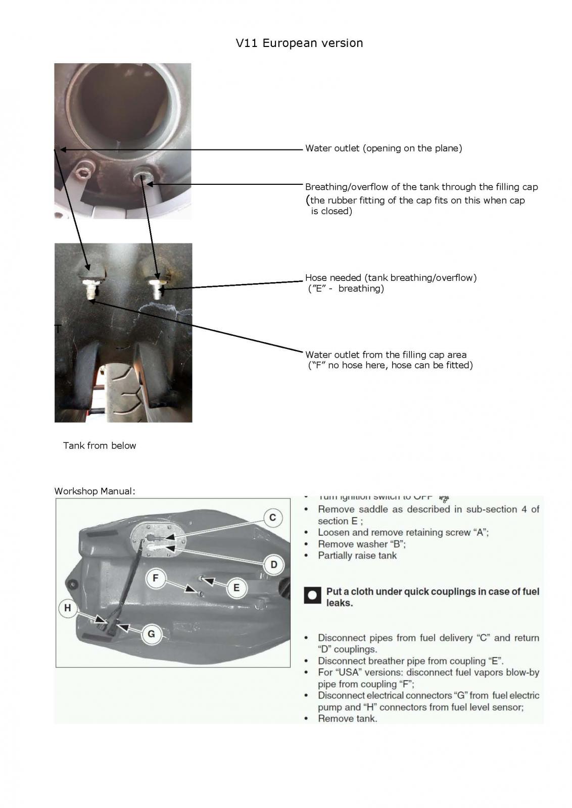
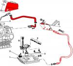
This is how it works on mine, "the European version". I read a good tip how to open a blocked vent hole. Take a wire rope (a thicker if at hand), put it to a drill. Some WD40 or equivalent into the hole and "drill" with the wire. Afterwards keep the route open by blowing with compressed air. The route which takes the water out is normally clogged. These instructions worked for me.
-
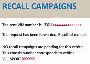
When you type your VIN number to this page http://static.piaggio.com/recall/form-piaggio_en.html You will get as an answer a verification, if there are any recalls for the vehicle active right now. At the same time the originality of the vehicle is confirmed: "This chassis number corresponds to vehicle "XXXXXXX".

-
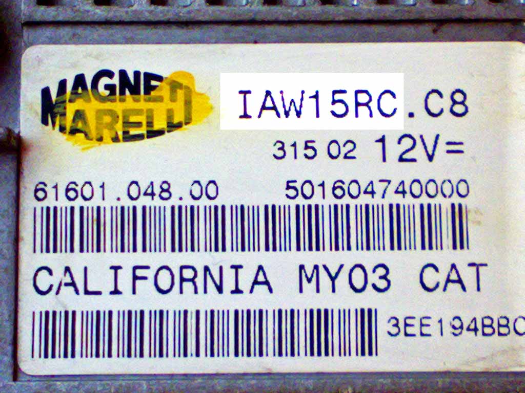
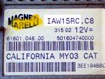
A guy who can say "trust me, I know" saw me when the motor was leaking oil from the sensor and his first words were "you have the O-ring in a wrong place". There is no room for it between the feeler itself and the spacer. The spacer get bent, no sealing surfaces. I'd bet you get good results by using both, first the O-ring to the motor Groove, and then some hylomar to all surfaces. The ecu type (15M or 15RC) is on the ecu sticker iitself.
-
On mine (-02,) there is a groove for the O-ring on the motor side. First the O-ring, then the spacers. I was dumb enought to do it vice versa and the oil leak after some 100 kms was huge... If you want to get it 100% leak proof, I'd suggest to add still a small amount of sealant. Done this way, mine is for the first time 100% dry. Worshop Manual: There are 7 different spacers available in various thicknesses. Such spacers should be selected, that there will be an air gap of 0,7 – 0,9 mm between the sensor and the teeths of the rotating wheel. I just read that GuzziDiag can tell (but only if the ecu is 15RC) if there are any teeth left "unread" when the motor is running (only when its running). This way it's possible to draw conclusions, if the feeler is too far away.
-
P = dry cleaning allowed (practically all solvents), the other to the right = no tumble drying. I have seen one where's a line after the markings: "Or give it to your wife".
-
I must be wrong then…. I found an earlier document of Kiwi Roy; there is an 'IFR 730A Mosfet (Q3)', which turns the charging light on and off: “as the engine revs, negative pulses from D6/D7 oppose the reference voltage and force Q3 to turn off extinguishing the warning light.”
-
A nice and educational drawing, specially and personally made for us viewers. My humble thanks. Still, for us non-electricians it is not so easy… just the charge light itself for example… I had to have it explained to me. The minus pole of the battery is not connected to the other side of the bulb wire as it is with every other pilot light on V11. There is the plus on both sides of charge light wire – but still a potential difference (different voltage), which makes the wire inside the bulb glow if the difference is big enough… If I did understand everything right. When my charging light started to have individual behavior last summer I just barbarically changed the Ducati regulator and that’s it. No trouble after that
-
I did the adjusting the same way. This is what the Workshop Manual says about it: “ Contrary to the previous model, the gearbox is equipped with a special adjusting eccentric “A” used to adjust gear selector hook “B” position. Gear selection will thus be improved and more accurate. Check that the area between eccentric “A” and hook “B” – marked on the drawing – is free. “