

Meinolf
-
Posts
160 -
Joined
-
Last visited
-
Days Won
16
Content Type
Profiles
Forums
Events
Gallery
Community Map
Posts posted by Meinolf
-
-
Hi,
if I understand your question correctly then the answer is easy.
Looking at the first relevant voltage entries 0.176V - 0.157V - 0.137V the delta is 0.019V and 0.02V respectively, so the range is +/-0.02V for the inital entries. However, let's not forget that we are looking at millivolts here. I doubt that the average DMM has the accuracy and repeatability to operate reliably in the millivolt and below range. Test lead resistance, tolerances of the ADC, accuracy of the 5V supply to the TPS and the general operation of an ADC came into play.
Cheers
Meinolf-
 1
1
-
-
Hi,
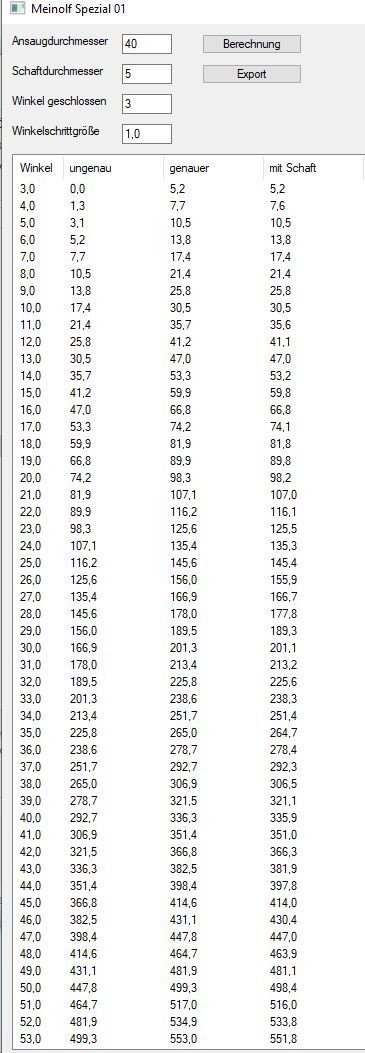
as to the question why more TPS breakpoints are used in the low range than in the upper. It's about flow area increase when the butterfly valve is opened. The flow area resulting from the movement is based on a rather complicated cosine formula, several years ago Beard kindly wrote a small program to simplify the calculation.
Looking at the 1st (TPS degree) and 4th column (free flow area in mm^2 including the butterfly axle diameter) one can derive the change in %.
7.7/5.2=1.46=46% increase
22.0/20.0=1,1=10% increaseSo, ~2.3 TPS degree change at low throttle opening result in 46% flow area increase, a 2.0 TPS degree change in mid range is 10% flow area.
It makes sense to use TPS breakpoints which provide the a like flow area increase.
Cheers
Meinolf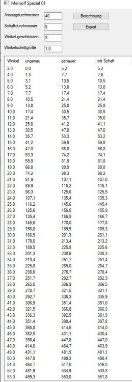
-
 4
4
-
2
-
-
8 hours ago, audiomick said:
...Meinolf took the time to sit down and do the maths....
Hi,
it didn't take that much time. The 157mV instead of 150mV is simply based on a rounding error in the OEM TPS lookup table.
5V/255=0,01953V
8x0,01953= 0,1563V=156,3mVNow one may argue if the 6,3mV difference is significant. No, it isn't. But why use a wrong value if the correct one is known.
Cheers
Meinolf-
4
-
2
-
-
Hi,
as rightly pointed out the 15M has neither the internal connection from the Lambda voltage signal pin to the PCB nor the code neccessary to process the signal if it were to arrive. And the RC code can't be uploaded to the 15M w/o bricking it.
But, the real problem lies elsewhere. The V11 engine was not designed with a Lambda of 1 as permanent value over a range of rpm/TPS in mind. It runs quite well with Lambda 1, but even slight changes to 1.03 are instantly and clearly noticeable. Not favorably, mind. The CARC models in contrast work well and one doesn't notice the same degradation. During my tests I oftentimes had entire regions of Lambda exceeding 1.1 without even noticing it, only the logged data did show it.
So, upgrading to closed loop absolutely requires a cylinder selective tuning of the fuel values to achieve a synchronized Lambda no higher than 1 on both cylinders. Which in my case extended over many months of datalogging and analysis.
Also consider the reason why a constant Lambda 1 and there closed loop operations were introduced before starting this journey. Emission control was the driver. The catalysator works best at 1 and has the highest conversion rate. If the cylinders are selectively tuned anyway to allow a closed loop operation, then closed loop is not required and the catalysator isn't there anyway.
Cheers
Meinolf-
2
-
1
-
-
On 10/28/2023 at 12:02 AM, ScuRoo said:
I disagree completely with these notions. The 15RC closed loop adaptability with STFT & LTFT trimming isn’t a backwards step in design. It’s a lovely plus plus on top of the base map - when the throttle is whacked open it operates just the same as the 15M base map as it’s now in open loop mode - but has the added closed loop constant throttle closed loop fine tuning.
There is zero problem with the 15RC ECU it’s lightening fast in response times - the original root cause problemo was “the LSH15 probe has such a slow response time to the variation of the exhaust gases”
…“the LSH24 instead has a very good sensitivity and a response time equivalent to the reading interval of the ECU.” The 15RC ECU.
Don't disable in trying to cure any hiccup stumble or poor running problems.
Just simply change the bloody O2 sensor to the improved LSH24 and you’ll have all the open loop 15M provides plus more with closed loop adaptability - which auto tunes out… any hiccup stumble or poor running problems!
Hi,
I fully agree with above. The main issue with the OEM BINs and their fuel values is the lacking synchronisation of the lambda (AFR) values between the 2 cylinders. If lambda is different between the cylinders at a given operating point the engine will not run as smoothly and efficient as it could in non-closed loop mode. If it's in closed loop the slow OEM lambda probe excerbates the discontent as differing lambda values are reported to the ECU from one combustion cycle to the next. It goes crazy trying to cancel out countermanding values.
Evening out the lambda values between the cylinders at any given breakpoints will achieve 95% of what can reasonably be achieved. Everything else is cream on top. And as the time needed for either is inverse (5% getting the lambda synchronity right/95% to for the rest),
Plus, this approach fits best to the OEM ignition values. I have no means of checking them, but guess/hope that Mandello knew better/had the required setup, to get these right.
Cheers
Meinolf-
5
-
-
On 11/2/2023 at 12:51 PM, audiomick said:
As mentioned at the outset, Guzzidiag shows you the numbers that the ECU is seeing. The ECU can't see anything below 3.9°, so that is the lowest value that Guzzidiag can report.
Hi,
Ok, some nitpicking from my side. The ADC does read smaller values. The way the correlation between TPS ADC values and TPS degree values works is that the ADC value is used to select a corresponding TPS degree value in the TPS Lookup Table, TPS ADC -> TPS degree.
I assume that the lowest ADC values are not used in the TPS Lookup table (0 values) as they are reserved for the error detection of the TPS signal.
Cheers
Meinolf-
1
-
1
-
-
On 10/26/2023 at 7:58 AM, Lucky Phil said:
I suggest you leave it alone. So all the V11 maps I've looked at, Meinolfs custom map, the std v11 from 2000, the Rosso Mandello, the factory map for the Titanium exhaust all use the exact same acceleration map numbers. I've never touched my accel map which is the same as the std V11 2000 map and all the others running a Daytona engine. The std 16M Daytona and Centauro maps dont even have an accel map.
Hi,
indeed the accel fuel map doesn't make a lot of sense. Consider the following. The accel function is only used if a TPS opening/closing treshold speed is exceeded. Quickly opening the throttle will lead to an main fuel value from the main fuel table which is larger than the one beginning with while the rpm remains unchanged for a a relatively long time. Which in turn means that the air mass (and its speed) moving to the combustion chamber will not change as rapidly.
The result is an increased fuel injection time while the air mass remains largely unchanged. Ipso, the mixture will enrich w/o any support from the accel enrichment map. And the accel enrichment tapers out with increasing rpm anyway.
Instead of meddling with the accel fuel enrichment changing the ignition values makes much more sense. A richer mixture needs less time to ignite, hence reducing the ignition advance while accelerating to move (or keep) the max. combustion pressure closer to TDC + ~12-15° is the way to go.
Cheers
Meinolf-
1
-
1
-
-
On 10/17/2023 at 6:08 AM, Rob NZ said:
The only issue is the underlying stock acceleration enrichment map which of course cuts in when you switch the Lamba sensor off.
Hi Rob,
the accel enrichment map is used also in closed loop operation if the opening/closing speed of the TPS exceeds threshold values.
Cheers
Meinolf -
On 1/23/2023 at 1:58 AM, PJPR01 said:
... disconnected throttle linkage and see the TPS is registering 0.350mv...well, that's supposed to be .157...
Hi,
350mV is in the range you would see if the TPS is not fully closed. If it ran well with this setting and not so after changing to 157mV then my guess is that you did not remove all the stops keeping the TPS from being fully closed.
Much success in resolving the bug.
Cheers
Meinolf-
3
-
-
Hi,
The ECU switches to communications mode when GuzziDiag or the reader/writer programs connect and the fuel pump will not spin up.
If the fuel pump spins then GuzziDiag or the reader/writer programs don't connect to the ECU. Two likely reasons, either the connector/adapter is the wrong one or defective or the plus/minus cables are not connectd. Or, in case of the reader/writer, the programs are not the ones to be used with your ECU.
Have you tried connecting GuzziDiag successfully? If yes, which ECU did you select? Are you using the reader/writer for this ECU?
Cheers
Meinolf-
1
-
-
On 6/19/2022 at 9:50 PM, arveno said:
Hello everyone,
I have a quick question regarding the
Air bypass screw on the throttle bodies.
Screwing it in or out does it lean or enrich the mixture?
I did some search but couldn’t find the answer…
thank you
M
Hi,
I haven't seen an answer to your question.
The bypass screw increase air flow thru the bypass when opened and vice versa. Which takes care of the air mass portion in idle and a bit above. The CO trim in/decreases fuel in idle and up to 3k rpm, which is the 2nd part of the AFR equation.
Some might remember that my BINs are based on completely closed bypass screws and 0 CO trim, the required AFR adjustment was done via fuel injection values instead.
Cheers
Meinolf-
1
-
2
-
-
3 hours ago, Weegie said:
Does the ECU vary the period it opens the circuit to the coils (or is it a fixed period regardless of any other parameters), prior to grounding it again?
Hi John,
the procedure as I understand it is as follows. The ECU goes thru an initial process to determine the engines rotational status. Eg, which cylinder is where and in which state, compression or emptying the bucket. This is governed by the toothed wheel attached to the camshaft and the engine position sensor and takes several engine rotations.
After the status has been established and verified the fuel phase table takes over. This table contains rotational degree values which are the starting point for the calculation of coil discharge and injector opening time. They are used in a backward calculation.
Which makes sense if one considers that the behaviour of any coil is depended on voltage (and coil design characteristics) and the logarithmic charging characteristics. So the tooth wheel and the missing teeth provide the starting point for the capcom-ops in the code which do the pulse-counting. This starting point (from a rotational point of view it's behind TDC) is in fact the point at which the circuits are opened again. Meaning, the point at which the discharge of the coil or the opening of the injector end.
So the calc looks like this:
Endpoint (fuel phase table value) + coil charging time/injector opening time = coil discharge start/injector opening
The code also contains a trim table to take care of the voltage dependencies. Eg, lower voltage requires a longer coil charging time/injector opening time to achieve the same effect due to the slower coil saturation.
So, the answer to your question "Does the ECU vary the period it opens" is yes, it does.
Based on the terrific analysis of the components used in the 5AM ECU done by John Th. we know that the current draw is used as another factor in the 5AM (and presumably later generations). I don't know if this current draw was already used in the 15M/RC.
Cheers
Meinolf-
1
-
2
-
-
Hi John,
On 1/6/2022 at 10:53 AM, Weegie said:I wonder if @Meinolf knows if the ECU switches the coils on and off and what the saturation times are,
I can probably contribute something, but need to know which ECU you are referring to.
Cheers
Meinolf-
1
-
-
Hi Pete,
Thanks for the excellent explanation, very well done.
Meinolf
-
On 9/20/2021 at 3:42 AM, docc said:
Unfortunately, Meinolf's map also specifies closed air bypass screws and very loose valve tolerances that I cannot accept. Perhaps his map is ideal for the atmospheric conditions and available fuels in his locale. I have to deal with my local conditions: sorry-corn-fed fuel and hot-humid air that is remiss to combust.
Hi,
the explanations here https://www.v11lemans.com/forums/index.php?/topic/23210-tps-reset/&do=findComment&comment=265226 may shed some light on the valve play/bypass screw topic.
The atmospheric conditions (baro pressure/ambient temperature) are taken care of by trim tables. I can't comment on the fuel quality, though. But, if it did then any combustion engine in your area would need a adaption, wouldn't they?
Cheers
Meinolf -
Hi,
allow me to step in and add some comments.
If I mentioned a valve play of 0,3mm for the V11 camshaft, then I made a mistake. The V11 camshaft is well designed and doesn't need any additional play to overcome (too) long slopes. The 0,3mm are recommended for all OEM pre-CARC camshafts, as they have a tremendously long slope. As a result the valves are slightly open for more than 100° CW before the actual opening cycle, with the accompanying loss of pressure in the combustion chamber and increased valve temperature for lack of cooling time with the valves connecting to the seat.
My recommended settings for the bypass screws and CO trim are only intended to simplify the usage of the BIN with different engines than mine. CO trim can be set accurately, but many seem to have problems adjusting it with GuzziDiag while the engine is running. I always choose the easier path of directly modifying the CO trim values in the EEPROM. The bypass screws are more problematical, as my 1/2 turn opening might be your 1/2+1/16 turn opening. They are not graduated.
The impact of CO trim (+/- fuel) and bypass (+/- air) is most pronounced a low TPS settings. So the idea is to avoid this potential pitfall, especially the potential mis-syncing of both cylinders. My BIN is based on AFR measurements and my targeted AFR targets for the respective breakpoints.
(Btw, I've revisited the 15M and to a lesser degree the 15RC code and found that the code contains a calculation which causes CO trim to taper off and disappear at 3000rpm)
Some may remember that the measuring and logging on the V11 was done with highly dissatisfying equipment form Innovate.
I eventually switched to Zeitronix, ZT2 and 3, which are much better, for my efforts with the Jackal and Norge. As this is mostly finished I moved the equipment to the V11 and started re-measuring it. The result is here: https://drive.google.com/file/d/1nIzV4LkFXJUyDMalLagnWb6c9I_0R0Bt/view?usp=sharing
Changes versus the 93_6 BIN are fuel values (improved AFR synchronicity between the cylinders) and changed ignition values (the engine runs less harshly in the 4-5k rpm/~15-30° TPS area. I will continue to work on the ignition, but since I have no means of measuring the effect except for my seat-of-pants, this is the area where the biggest remaining improvements are hidden.
I've also noticed that, after re-working the butterfly valves and the shafts, there's an much larger than expected discrepancy between fuel values over the first two TPS breakpoint columns. As I intend to open the engine anyway to inspect the valves, I'll revisit the throttle bodies as well. This is mostly a cosmetic issue, the bike runs splendidly.
But first the rebuild of the Mille GT (change to a BMW K100 fork with 41,3mm diameter instead of 35mm, new camshaft, improving the valve timing, ....) and the SPIII rebuild after I was crashed by a young Italian lady in the hills above Genua have to be finished.
Cheers
Meinolf
-
4
-
4
-
-
On 9/18/2021 at 6:08 AM, Lucky Phil said:
I looked at the ignition map from the .bin file Meinolf posted here about 4 years ago and the ignition numbers around the area we are talking about are nothing like the std map FWIW. Caveat to this though, when I looked at the main fuel map it looked a bit weird so I dont know what the issue is there, maybe my IT skills. The ignition map looked normal but very different to std. He also uses different throttle and rpm load points as well. Maybe he'll be along to explain at some point.
Ciao
Hi,
maybe this will clarify some of the questions. AFR/Lambda and ignition timing are closely intertwined. The flame through speed of the mixture varies with Lambda, up to -20%.
The fuel values in my V11 BIN are based on a Lambda target map, which is based, amongst other considerations, on MAP at the respective breakpoints. I use a meager mixture at low MAP breakpoints and richer mixture in areas with less throttling loss.
Hence the fuel values vary a lot from one breakpoint to neighboring ones if this is where the target lamba changes from 1.0 to 0.94 (as example). This variation is most pronounced when moving from the fuel shut-off area (better engine breaking) to the fuel-injected areas.
The ignition values reflect the mixture. Meager mixture = earlier ignition, richer mixture = later ignition.
The earliest ignition values are used in the fuel shut-off area to minimize popping in the exhaust, which is caused by a lean mixture not igniting in time.
As to the thread topic - the hiccup. If no other faults, most of them were already mentioned in this thread, are present, hicc-ups in my experience are always the result of a lean mixture. The V11 engine runs reasonably well with Lambda 1, but deteriorates quickly if the mixture gets leaner.
Cheers
Meinolf-
2
-
4
-
-
Hi Phil,
Countersunk is factory standard, so a PO probably recognized the problem.
Yeah, first grandchild and me becoming a semi-grandfather. So to say. And the little loves me, I bear scratches in my face as evidence

-
On 9/1/2020 at 11:56 AM, Lucky Phil said:
You only need to remove 2 screws on one throttle body lower brace as this will allow both to be removed and both ends of the upper steel brace which as I said the screws remove easily.
Hi,
While re-reading Phil's post one more thing came to mind.
The throttle bodies, when fastened to the braces, are not well seated in the rubber thingies (can't remember the correct term). In other words, the screws and threads in the braces don't align well. They can be forced in, but then the throttle bodies sit slightly twisted in the rubber boots (ha, memory came to the rescue). Enlarged screw holes and regular cylindrical inbus screws seating on top of the braces allow for installation without tension and offer the benefit of screw heads which won't self-destroy during the next time the TBs are removed.
Cheers
Meinolf
PS I'll post a picture when back in Germany. Just now I'm living the good life in a cafe in the old town of Limassol on Cyprus, visiting my mate's daughter and the first grandchild
-
1
-
-
Hi Phil,
thanks, a very lucid and detailed explanation. I re-worked the throttle bodies of my Jackal and V11 some years ago, some additional comments based thereupon.
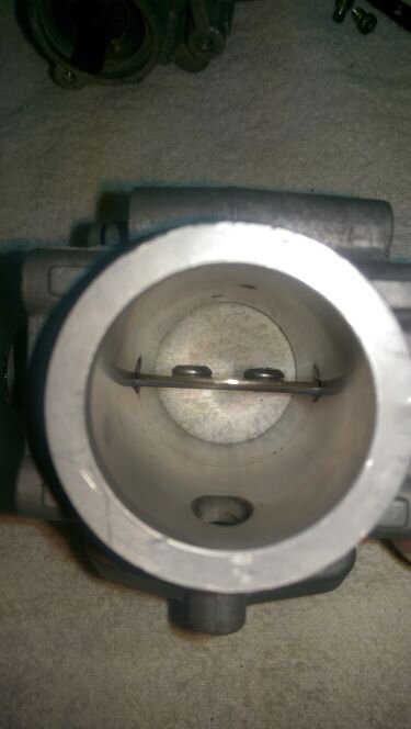
This is important, the butterfly valves have edges ground at an angle to fit to the throttle bodies when closed.
8 hours ago, Lucky Phil said:Mark the throttle plate so you can install it in the correct orientation.
The original screws block a substantial amount of the cross section, the two pictures (before/after) show the difference. Using flat-headed screws frees up some of the cross section, especially if the screw is selected (or made to fit) to the diameter of the shaft.
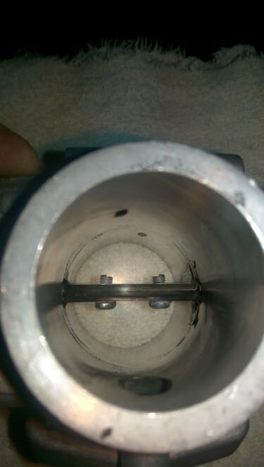
For those willing to go further, one half of the shaft can be removed. Freeing up even more of the cross section for increased airflow.
Cheers
Meinolf-
4
-
2
-
-
Hi,
I'm not sure if I know what you mean by “world spec”. The service manual recommends 0.15/0.1mm for exhaust/intake, I use 0.2/0.15mm respectively. But it's not critical in regards to my BIN.
Cheers
Meinolf-
1
-
-
Hi,
I still get emails asking for the V11 BIN I made available several years ago. I can't find my post with the download links, which don't work anymore anyway, so here's the current download link.
https://drive.google.com/file/d/1e7MMuO6vrUZGFfmkCtL3zsW1qeS6uDgY/view?usp=sharing
The base setup, and that's quite important to follow to get the best results, is:
- TPS set to 157mV with all mechanical connectors removed and throttle completely closed
- Both bypass screws completely closed
- CO trim set to 0
- Idle sync with both (if so required) throttle stop screws
- Running sync as usual
And while we at it, here's the link to the Jackal (works with any California with 15M) BIN. Same base setup as V11, but I recommend a larger valve play of 0,3mm for exhaust and intake. The Jackal BIN is quite recent.
https://drive.google.com/file/d/1Wb2LXrRrgDI1WO0krnb_GeiAvewbwA1K/view?usp=sharing
Cheers
Meinolf
-
6
-
5
-
-
Hi,
1 hour ago, docc said:I am uncertain, now: Is the TPS baseline target 156 mV or 157 mV?
it's 156.25mV or, if total accuracy is targeted, 8*(5/256) with as many decimals as can be successfully measured.
Much success
Meinolf-
1
-
-
Hi,
my valve play recommendation of 0.25mm valve play is based on the measurements done on the V11 camshaft. Less play leads to a much longer period at which the valves are already slightly opened. The effects are loss of mean pressure in the combustion chamber and less time for the valve to conduct heat to the seats. My V11 has run more than 85.000km with this setting.
0.157V as base setting for the TPS is recommended because the ADC in the ECU is a 8bit version. 5V are divided by 256 ($FF), which leads to a step of 0.01953...V. Multiplying this by 8 leads to the 156(.25mV). The 150mV found in the Guzzi literature is wrong, somebody at Guzzi or Marelli made a rounding error. I'm not saying that achieving 156mV is critical, to many factors including the quality of the DMM used come into play. But why not choose the correct value, if it is known, as target.
Cheers
Meinolf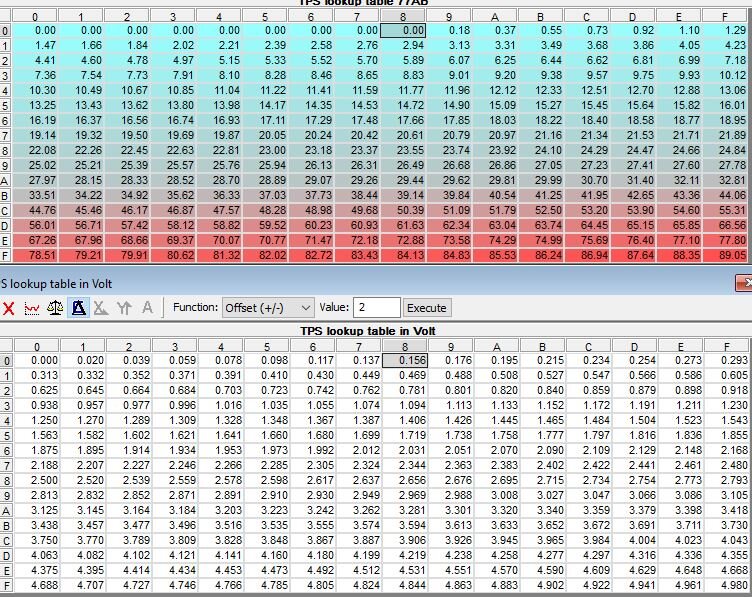
TPS break points at low throttle openings
in Technical Topics
Posted
Hi Mick,
no, 15mV tolerance is not sufficient. The total spread between the first breakpoints is ~20mV. Assuming you are off +15mV from 157mV would put the TPS well within the range of the next breakpoint; target missed.
Even +/-10mV is stretching it thinly, +/-5mV is the highest tolerance I would go for.
Cheers
Meinolf