All Activity
- Past hour
-
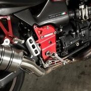
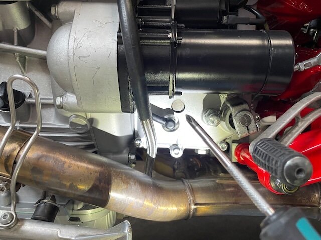
Hi friends: I have a 2001 Greenie I've been working to bring back to life (thanks for all the forum assistance and info). I've ridden it a bit around town, and have one current oil leak that I'm hoping for advice on. It's on the left side of the transmission case, visible just under the starter, adjacent to and slightly above the neutral warning light. It's a circular piece of steel that pokes through the case and is a little recessed (see photo - I'm pointing at it with a screwdriver). I have a manual, but can't see where that piece is named anything in the Section N Gearbox chapter. It does show up in one VERY small diagram there (see photo - I'm pointing at it with an Xacto) on p. 26 section N, but I can't work it out. And because it has no slot or fastener head on it, I'm struggling to imagine how to get it out (to put on a new o-ring or whatever) other than take that side cover off. Before such bold exploratory surgery, I thought it's best to ask :). Attached are a couple photos. The leak is just a small drip, but it does run down the side of the case and onto the pipe. I haven't ridden the bike extended miles yet, but am concerned I'd end up on the side of the road out of town with abundant hot oil on the outside, not the inside of the tranny. It does form a drip VERY slowly, maybe once a week, while cold in my garage. All advice appreciated!

- Today
-
My 2001 has 1mm above. I don't think it was ever monkeyed with because nothing else was ever changed on it. I wonder why there are such variances in the later bikes with the Ohlins.
-
 That's rather nicely put. I'm presently in the Isle of Man which has many parallels with the north of the UK. History at every turn, and picture-postcard views in every direction. The natives are friendly too. Tourism plays a diminishing part in the economy. It's certainly not like it was in George Formby's day. So we survive by helping the super-rich stay that way, and housing most of the UK's online gambling companies...
 -
So for the 99-2001 bikes the distance is 3mm above the top triple and for the later Le mans and V11 Sport 2003 it's 36 mm and the Ballabio its 32mm. For the Ohlins bikes it's 30mm for the Rosso Corse and 26mm for the Cafe Sport. These are all starting points of course. The only thing to remember is if you raise the forks through the triples you need to make sure you don't run into ground clearance issues and the front guard hitting the oil cooler on full bump and that you still maintain the full 54mm fork OD dia in the lower triple clamp.
-
My Coppa has 15mm above.
-
So, what is the factory dimension of the fork stanchion above the triple clamp on the later V11? Is the 2002/'03Carryover dimension different from the later V11 forks?
-
Yep. My bikes front end is basically the later long fork and top clip-on version.
-
Here is a good example of how far the later LongFrame forks are above the top clamp from the start. Same from 2002 on?
-
The fork length varies depending on whether your bike has the clip-ons mounted above the top clamp or below. So the later bikes with the 43mm forks and top mount clip-on have forks 19mm longer in free length than the earlier swan neck clip-on bikes. The extra length is to accommodate the clip-ons above the top clamp obviously. Ohlins legs are 3mm longer again than the Marzocchi 43mm forks. So 22mm longer than the early forks. Phil
- Yesterday
-
I measure 22mm on mine and the fork cap is not included in the measurement . I also do not know how long the red frame v black frame forks are.
-
Cheers Doc, yeah I thought it best to measure it this way too....ie not including the cap. Be interesting to hear about the long frames eh.
-
If were talking about the early V11 with the clip-ons mounted below the top clamp, the forks are factory mounted with the top of the fork stanchion level with the top of the triple clamp and the cap standing proud. In this case, I suggest we measure any change from the top of the triple clamp to the top of the fork stanchion, not including the cap. Beginning with the 2002 LongFrames, the clip-ons are mounted above the triple clamp and, therefor, the forks are already raised above the triple clamp to clamp on the clip-ons. Whatever that actual dimension is should be the baseline to subtract from any alteration to get the actual change. Again, I suggest not including the cap. Can anyone confirm the amount of fork already above the triple clamp on a LongFrame V11?
-
@Cold Desert Rat, Is the carbon fiber one aftermarket?
-
G'day Mate I did see your post about that! Just out of curiosity...how did you measure the 15mm? I have 15mm from the top of the fork cap to the triple clamp. Given that the cap is 3mm means I have 12mm of actual fork above them. I'm pretty happy with it like this! Cheers
-
 Indeed! I don't remember having had such a nice riding weather for a long time. Last Sunday, I went to Brenham myself.
 -
I didn't read this entire thread, but if you search my past post, I write a bunch about this subject; set-up, SAG, suspension, etc.. I ended up at 15mm.
-
https://www.ebay.co.uk/itm/256686685576?mkcid=16&mkevt=1&mkrid=711-127632-2357-0&ssspo=z2laZvJuS16&sssrc=4429486&ssuid=z2laZvJuS16&var=&widget_ver=artemis&media=COPY
-
 2mnyVoices joined the community
 - Last week
-
 I was tempted to go...just back from 10 days in Italy with the family, but unfortunately I have commitments all day Saturday. The ride out there is thru some very nice scenery...hopping over to Louisiana over the Taylor Bend reservoir is a very nice ride indeed! The weather is absolutely superb...I hope to get out on Sunday for a nice long ride...
 -
I have been pondering if this would be the case for a week now. Thanks!
-
And it I make a point of using all of them as often as possible.
-
It looked to me like after the bonzai pass a couple laps from the end, the guy in second settled for second as it was good enough. Smart.
-
The original broadcast of the race on TruTV / TNT Sports ran into an issue. It was on right after a baseball game, which ran way late. They did not delay the coverage of the race but rather just cut to the race when they were finally done with the baseball game. I set my DVR to record it but since they did not delay the coverage of the race all my DVR got was the end of the post race coverage. Luckily I did not see who had won. But TruTV / TNT Sports typically re-airs the MotoGP race on Monday. So we were able to watch the full coverage of the race last night. Sadly, I stayed out of this thread as I did not want to spoil the race, so it is too late for anyone who still hasn't seen it to catch it last night. Hope everyone got to see it. P.S. F' baseball! I would rather watch grass grow. Or paint dry.
-
Here's the flyer from the Texas Ride Magazine: https://www.ridetexas.com/event/flying-g-motorcycle-museum-grand-opening-2/ I am planning to be there using some kind of form of transport which is left undecided as I am typing this; 2 or 4 wheels. Joaquin is very close to Louisiana, with a bit of imagination Arkansas, bit more Oklahoma... Current Texas weather is incredibly good, at least here around the Bayou city. I believe it maybe cooler up in the northeast part, in the woods. If you decided to come there, you will find me in a red vehicle, with either 2 or 4 wheels. I should think, given past experience, than no many have red bikes or cars...
-
I don't think we should be surprised; the guy has some incredible qualities, resilience, combined with experience. At the beginning of the season, it seemed that Pedro Acosta was going to be his natural heir; however, in view of the latest performances, we may need to revised the judgement on this one. Well, without being harsh of course. Pedro is still in his rookie year in MotoGP. Now, let us not forget that Philip Island is a counterclockwise track, immensely favored by MM. New asphalt meant unknown conditions, again a factor where MM shines like nobody else. I think it is a given that he should be at the top of the list of the potential winners for the 2025 title.
-
New dealership, Moto Bello, Orange County, California
p6x replied to LaGrasta's topic in Travel & dealers
Exactly that! In fact, nobody really knew that Piaggio existed, as Vespa was just a product that became a brand name; same as Frigidaire for refrigerators. Hoover for vaccum cleaners in the UK. But today, Vespa is its own brand, and Piaggio makes scooters too.