

Miro Kacur
-
Posts
13 -
Joined
-
Last visited
Content Type
Profiles
Forums
Events
Gallery
Community Map
Posts posted by Miro Kacur
-
-
19 minutes ago, docc said:
I see no value for the lock nuts in the Workshop Manual on the torque value page nor the swingarm section ("Assemble in reverse order.")
You are right. That means I might have to rely on my gut feeling in this case. That is unless someone will clarify his/her experience on this topic.
-
 1
1
-
-
Anybody please know the torque setting for those big lock nuts that go onto the pivot bolts. You know, those lock nuts that tighten the pivot bolts to pork chops...
Thanks a lot!
-
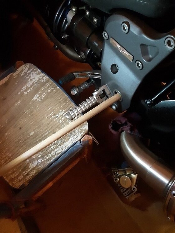
This might seem obvious to many. When I was reassembling the swing arm into the frame I found useful to put a wooden stick thru the frame hole and swing arm pivot hole on one side – to align them as much as possible (please see the picture).
Then I was able to correctly screw in the pivot bolt on the opposite side more easily. Of course, I had the swing arm top section already attached and fixed to the shock absorber.
-
1
-
 1
1
-
-
On 11/7/2022 at 10:35 PM, MartyNZ said:
I'd try fitting the left pivot pin from the inside, so that the pin swages the damaged outer few threads into line. After that, wind that LH pin out enough to fit the swingarm and RH pin.
If you use a tap to recut the threads, you risk having a loose pin if you don't use the correct tolerance tap.
Dear All,
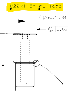
I got a reply from Piaggo regarding this and the thread for the pivot pin is M22x1 with 6h tolerance - please see the drawing attached.
So I am assuming that the correct tap for recutting the female thread in the pork chop hole would be M22x1mm 6H (Metric Fine Thread)Miro
-
3
-
-
20 hours ago, MartyNZ said:
I'd try fitting the left pivot pin from the inside, so that the pin swages the damaged outer few threads into line. After that, wind that LH pin out enough to fit the swingarm and RH pin.
If you use a tap to recut the threads, you risk having a loose pin if you don't use the correct tolerance tap.
Thank you Marty,
Just for the clarity, here I found a similar thread in this topic: https://wildguzzi.com/forum/index.php?topic=104932.0;prev_next=prev#new
-
1
-
-
On 6/21/2015 at 4:26 PM, gstallons said:
When you replace the swingarm bearings , remove the dust shield of one side of the bearing and fill it completely w/wheel bearing grease . Put the dust shield back on and install this side in away from the outside of the bike. .Roller bearings come w/just enough grease to not rust. This bearing is not going to roll but pivot a few degrees throughout it's lifetime so grease is going to make it last from now on.
When you are ready to install the pivot pins grind a bevel or taper on them so they will go through and into the bore of the bearing easily. If you crossthread these pins , just remove the swingarm and screws them from the inside out to clean up the threads .
Good luck & keep us posted !
Hello everyone,
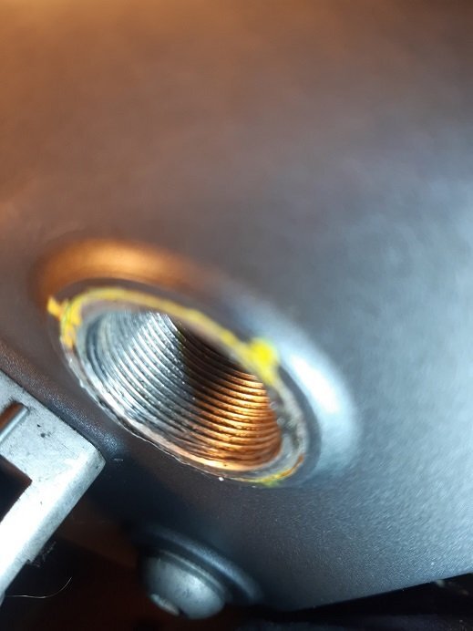
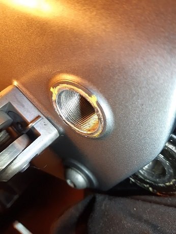
While installing the pivot pins I have accidentally cross threaded the left one. In my opinion it’s nothing major, only the first two threads are affected however it is enough to prevent the pivot pin to line up and to easily screw in. (please see the pictures included, the damaged thread is at about 6 o’clock in the very entry to the hole)
I am thinking about rethreading the pivot hole from the inside with a relevant threading bit. Does anyone have experience with repairing the swing arm pork chop pivot holes? I am assuming it’s M22x1 of metric fine thread – but I will gauge it properly of course.
I am expecting to screw in the threading bit from the inside, where the threads are ok. This way the threading bit will line up with the existing threads and it will probably go thru easily for about 95% of the hole length. Only then it will hit the damaged threads and cut thru them. So much for the theory 😊
Anybody attempted to rethread these swing arm pivot holes?
Thanks for your advice/opinion.
-
1
-
-
On 9/3/2022 at 2:32 PM, Miro Kacur said:
Thanks, I will evaluate the options and let you all know which one worked out for me
")
Dear All,
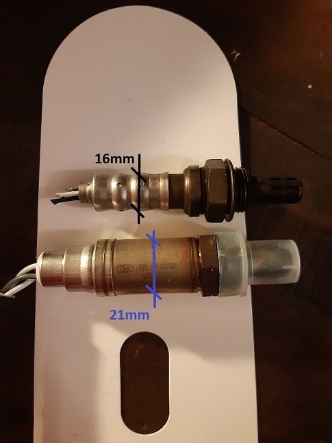
After weighing all the options I found the most feasible solution to replace the faulty stock O2 sensor with the BOSCH Type LSH 24, LS 6206, part.no 0258006206, length 325 mm
The „collar“ of the above mentioned sensor is 18mm which is slightly wider than the original stock sensor’s 16mm (for full details see my post from Sep 2 above), nevertheless, it fits in the place. I don’t have any info about actual performance because I need to reassemble the rear drive, put the wheel back, etc…
So to recap -> if you are to replace your stock O2 sensor on V11 Ballabio 2004 (in the post above I have wrongly stated that I have Ballabio 2003, but in fact I have 2004) with stock cross-over, you might have to opt for the BOSCH Type LSH 24, LS 6206, part.no 0258006206, length 325 mm which is the one that can fit in the tight space and does not interfere with the engine block frame.
Miro
-
2
-
1
-
-
Thanks, I will evaluate the options and let you all know which one worked out for me
-
On 8/20/2020 at 4:46 PM, ScuRoo said:
Okay... before I go further - on my bike the O2 sensor site was relocated on the left header just in front of the oil dipstick when a MassMoto X-over was installed. The existing O2 sensor was just rerouted to that location.
Whilst my bike was noticeably freer-breathing from mid revs all the way to redline and my riding habits had shifted up the range by some 500-1000rpms - what should be noted was that there was no real actual change to my bikes modus operandi style in the low range.
There was that occasional fart, sometimes a stumble, a miss... all the usual things that’s inherent in our V11’s character.
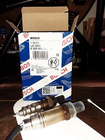
However, after translating Ube’s 2006 posting recommendation I set to sourcing & pricing up the genuine Bosch LSH24 sensor identified as the LS3805 aka 0258003805.
Removing the existing sensor it was a surprise to find it was an NTK OZA341-BB1 sensor. More research subsequently revealed this was the NTK manufactured equivalent to Bosch‘s LSH15 calibration curve.
After install for the first two rides on seperate days an adaptation procedure was followed:1. Start engine & allow to idle for 5 minutes.
2. Drive vehicle for 5 minutes between 20 & 30 MPH. Do not allow RPM’s to exceed 3000 RPM’s.
3. Drive vehicle for 15 minutes between 40 & 60 MPH. Do not allow RPM’s to exceed 3000 RPM’s.
4. Stop vehicle & allow to idle for 5 minutes.
(It’s late - be back tomorrow... 💤)
Hello ScuRoo, were you able to fit the Bosch LSH24 0258003805 sensor in place of the original O2 sensor? I have a problem with the diameter of the Bosch sensor collar, it is pushing against the frame in place where the original O2 sensor was ok. Please see my reply to the topic at the end of this thread – there are pics explaining the issue. Thanks for advice
-
1
-
-
Hi all,
What is your experience in fitting the Bosch LSH24 0258003805 sensor in place of the original O2 sensor? I have a 2003 Ballabio with closed loop O2 sensor and original exhaust. I have discovered that the original O2 sensor was faulty so I am in the process of replacement. I was following the recommendations of ScuRoo here on this thread I acquired the Bosch LSH24 0258003805 sensor, however, the Bosch LSH24 sensor has slighly wider collar and I am not sure if it fits in the exhaust hole. The collar is simply too wide in diameter and is pushing against the frame bar. Please see the pictures for better explanation. The original O2 sensor collar is 16 mm in diameter and the Bosch LSH24 0258003805 sensor is 21 mm.
Anybody experiencing the same problem and if so what was your remedy?

-
 1
1
-
-
Thanks Kiwi_Roy, I have made my own marks on the joints. Along the way, I have also marked many fasteners just in case that I wasn't able to find out the correct torque settings, I could just tighten them to their original position.
-
Hello there,
Being a new here, let me start by thanking you for this and many other threads I have been consuming on this forum.
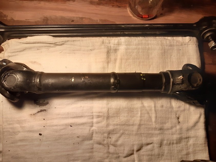
I have followed your instructions and decided to take off the whole swing arm, just to grease the drive shaft. No problem with that whatsoever. After inspecting the drive shaft I have notices small flakes of paint peeling off (pics included). Nothing major, but still, me being a detailist, I would like to treat, just to have a peace of mind. I don’t think I need to go as far ar coating the whole drive shaft. I was thinking about applying a small amount of coat only locally where needed. Have you treated the shaft (or maybe other parts such as frame, et al) with locally applied paint and if so, what paint did you get the best results with?
(If this topic belongs to other thread, I will be happy to remove it from here)
Thanks in advance.
Miro
-
1
-

TPS Reset
in Technical Topics
Posted
So in other words, I cannot rely on GuzziDiag mV reading when physically adjusting the TPS ?
I was getting +8mV higher reading on GuzziDiag vs the voltmeter (521 mV voltmeter / 529mV GuzziDiag)
The question is, which of these two instruments should be taken into account the GuzziDiag (v0.60) reading or the voltmeter ?
Thank you for clarifing.