

Stick
-
Posts
109 -
Joined
-
Last visited
Content Type
Profiles
Forums
Events
Gallery
Community Map
Posts posted by Stick
-
-
I posted this "no bleed method" on Ducati.ms to remove the narsty air bubble up near your master cylinder:
You may want to give it a try.
-
A while back I identified a Hall Effect TPS that should fit the Guzzi. The nice thing about Hall Effect is it has no sliding parts, the angle of rotation is transferred magnetically so it should last forever.
Digikey have HE TPS units for around $40 but the problem is selecting the right one, a while back I purchased a Honeywell one that looked like it would work but it was just a tad too big.
Digikey part no 693-1001-ND or 693-1003-ND look interesting, they have an output of 50mV to 4.5 Volts
The curve doesn't have a knee though, it's strictly straight.
Points to consider
Rotation degrees, I think 180°
CW or CCW rotation
Spring loaded or not
The slot or tang to fit
Hall Effect TPS millivolts doesn't start quite as low as the old slidewire type
Perhaps an expert like Meinolf could write up a spec for a new Hall Effect unit
The map might need to be modified slightly, I don't think Hall Effect has the same knee in the slope
The second paragraph d) "you can use any TPS that can be fastened to the throttle body"
should we also say any TPS that is readily available
I looked at these 2 on DigiKey. I don't believe they'll work, because it says the rotation angle is 0° ~ 360°, Continuous. I believe ours is more like a 90 degree rotation. And, it says "Clockwise increase" .
Agree, though, that Hall effect would be very cool--no "wiping" contact.
Stick
-
 1
1
-
-
Never forget that she likes to drink a lot, so be sure to keep her tanked up !

-
I've seen a slight difference in needle tip colors also. Mine had 8K when I bought it a couple of years back. Now it's a bit over 15K.
-
I don't like the fact that you saw a small spark when re-inserting the 30A fuse. That tells me you have some leakage current back to the RR.
IT'd be nice to know "how much". Easiest way to measure is to substitute ammeter probes in place of the fuse. If you don't feel comfy doing this, have someone more familiar with handling a VOM, and have them do it. The leakage current should be less than 3 mA (that's 0.003 A)
It may be the RR, even though it's "new", may be on it's way out.
Note that I'm using a 3-phase RR in my Lemans. It was a spare I use to carry on my DUC ST2. Never needed it ('till I got the Lemans!!).
I just used 2 of the 3 yellow wires on the RR (these are the AC wires). Charges nicely now at 14.2V. The RR is cheap second hand, maybe $40, and it doesn't need a ground. It's got 2 red output wires, adn 2 green output wires. Green are the ground (minus wire back to the battery).
The only thing "bad" is the fact that you don't have the charge light any longer. My Escort 8500x50 has a built in Voltmeter, so I'm happy.
Oh, I also agree w/ the above to add a better ground to the OEM RR. I believe the OEM one NEEDS a ground to function...
-
When you get the "clack", but no rotation, if you hold the starter button, it will eventually blow the 15A fuse. The solenoid draws a high initial current until the starter is rotating. Kiwi Roy may have a better expl. on this one. But I've seen it on my V11. Just try not to hold the button more than 1 second when attempting a start when you get no initial cranking. Wif, when this happens to me, I will repeatedly hit the button, until it does crank.
And I'm not sure if this is the same thing as "Startus-interrupus". Maybe Mr. Roy can answer that question, too.
Note that there is also the CLACK where the starter will never rotate. This is where the field magnets become un-glued on the stator, and crash into the armature. Not a lovely sight, when you open up the starter to investigate.
-
1
-
-
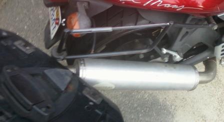
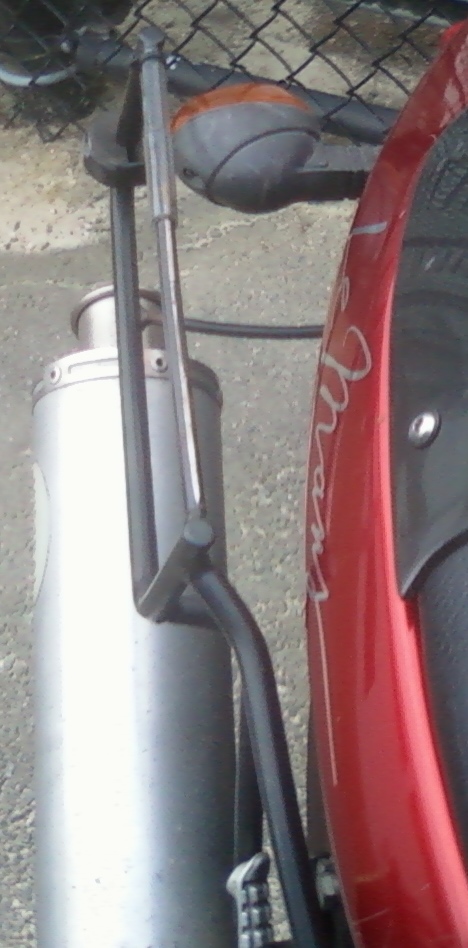
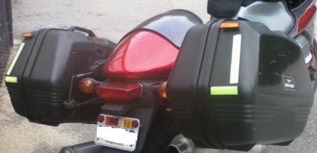
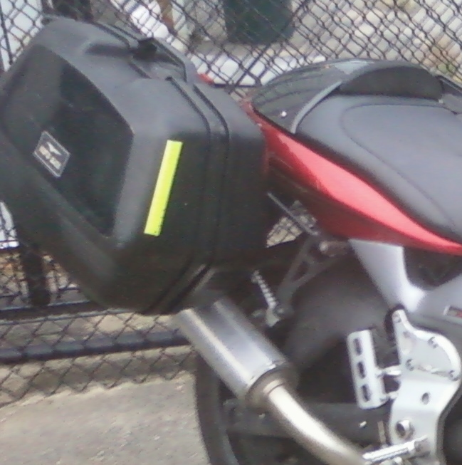
And 2 more pics of the rack vs. the indicator light:


-
1
-
-
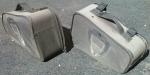
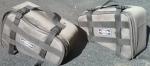
A few pics showing what I did with my Tekno clapped-out bags - Turned them into hard luggage!


-
Any chance you could post a picture or two of just the mounts that show how they are attached ? Are the rear turn signals relocated or are the mounts wide enough to clear them?
Mounts are like thick wire frames. Maybe 3/8" dia. "wire", a bit thinner horizontal area where the mount clips on.
Oh, no need to relocate the turn indicators.
Here is a pic of where the clip mount would be.
Cy: If you can live with the white or natural color, then the cutting board will do!
-
"the bike I saw that started it all - although there was no girl for additional inspiration"
That photo, enlarged and mounted in my shop, would have been the inspiration !
-
1
-
-
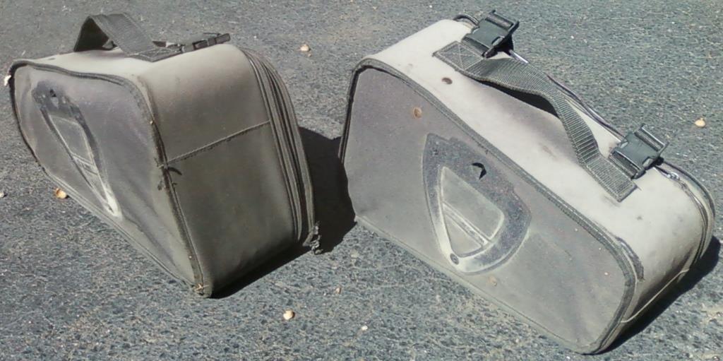
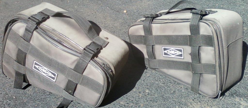
Tekno was the popular luggage and mount system for V11 machine, back in the day. Here's a pic of my clapped out bags that came on a bike I bought (and since sold). Very sun-bleached and one w/ bad zipper.
Luckily, the bike looked much better than these bags!
I removed the mounts off the back, and used them on hard luggage on my newer Lemans. Now, if I could only find THAT pic!
Oops, Sorry Docc, I was shrinking the photo size, and didn't see UR reply!
-
Email them the photo, and see what they say? Also, perhaps suggest they ship you a new one, before you ship the cracked on back.
Maybe pre-pay for the new replacement, and then get refund when they receive the cracked one?
Just some ideas. Not like it gets you out there running with these a ton sooner...
-
". I read somewhere that the threads that it screws into can be problematic."
agreed. mine was buggered. wouldn't tighten up, wouldn't come out. just flops a bit. I left it, ground wire between two nuts. the tach works fine.
Yes, very similar on mine. The stud was a bit loose - hence gnd. lug loose. Could not be tightened or removed. I added another lug to a separate screw, and made sure it was grounded. Worked for me.
-
I can't recall the reason I needed to dig into my instrument cluster, but I was appalled at how crappy the ground connection was made to both tach AND the speedo. I ended up "installing my own" grounding wire to a real screw inside that area.
If you've never been in there, I imagine Gino did a similar, crappy job on yours.
-
I had hoped to check a few V11 at the South'n Spine Raid (there were eight!), but it proved more cumbersome than I thought. (*Other* TechSessions prevailed!
 )
)I did hit mine with the IR reader and found the 2nd/Headlight Relay and 4th/ECU Relay about 125ºF and the 5th/FI Relay ~147ºF. That difference would be quite discernible to the fingers, let alone the lips
 )
)Seems the 1st/Starter Relay and 3rd/Neutral Relay were ~115ºF. ("as I recall . . ."). I did not compare that to the surrounding materials.
I didn't have time to take notes, so may try to get another reading when things aren't as pressing.
Thanks for the redundancy check, Docc. And with an IR temp reader. Your temps seem pretty warm, warmer than I thought I was feeling. Maybe 'cuz yer "down South". I got to find my IR reader.
But it's good to know that it's just not my machine.
Thanks again,
Stick
-
Thanks guys! I'm just trying to get a feel for this one to see if it's "normal" or not to have that one feel warmer than the others, that are "always on with engine running". So I assume that it's not the relay's coil producing the heat...because the others are always energized (except for the starter relay #1).
Stick
-
I pulled the seat off after a ride last week, maybe 1/2 hour of seat time. I was attempting to wiggle the relays to see if I could make my headlight misbehave ( This season, I placed a 20W LED H4 replacement in there...)
Anyway, I noticed that the rear-most relay seems to be notably warmer than any of the others. The rear one probably carries the most continuous current, since it's powering the FI pump, coils, and injectors. I'd guess about 8 or 9A, but I have not measured it yet.
I do carry spare, new relays that I ordered from Digi Key. I think they're Omron brand. So I swapped in a new one. Checked it again after another 1/2 hour ride, and see that it is still warmest. Not super hot, but definitely warmer than the others. Granted, #4 does the ECU and #2 is the headlight, so I'm guessing there's less amps going thru those.
Has anyone else noticed this?
 Or would you like to see if your rear-most relay is warmest? Or do I have to assume I have a marginal connection in the socket?
 I did dissect the old relay, and it shows no sign of bad contact of overheating of any sort (visual and scent).
2002 V11 Lemans w/ 15Kmi.
Thanks in advance,
Stick
-
Wait . . . the early V11 motor can be made an oil squirter by changing the rods?
I didn't know how that was done.
Put your readers on, and look carefully for the small squirter hole up a bit on the rod. It uses the oil going to the big end of the rod.
-
1
-
-
Hi Tom,
I do have black front forks, and I think they're Marzocchi . One set of pinch bolts on the right fork, and the left fork is threaded (Axle threads into it).
I still have the issue of the spacer on the right being slightly loose. And this is after torquing the axle to about 70 ft-lbs. The good news is, is that the wheel does not seem to want to float left-to-right. I've checked this and cannot pull the wheel to the right, while having my knee putting force at the axle area and pulling the wheel with both arms, on the right side.
Thanks for the offer! I may take you up on it.
I have this Friday off, and am heading to Western CT to care for my Mom. If Friday doesn't work, maybe Sunday PM? Or some other time?
Wanna give me a call or text? 508-340-9282 Verizon cell. New building at work blocks signal from 8a-5pm. Ok to about 9pm.
Mike "Stick"
-
When I noticed my "new" 2002 Lemans was charging too low (12.5V), I went thru the charging circuit starting at the stator. Dummy loaded the stator to ensure that the 60VAC I was seeing was "real". Then I decided to swap in a spare Ducati 3 phase RR that I use to carry on my Duc ST2 "just in case". You use only 2 of the 3 yellow wires on the newer RR, and tape the 3rd one. This RR works great - it charges at just over 14V, and the AGM battery is very happy with this.
You can find these for less than $50 used. (eBay, Gotham Cycles, etc).
The only downside is that you don't have the GEN light any more. I use the voltmeter function built into my Escort 8500 x50. "Never leave home without it." ;-)

-
Here is the file I was trying to attach. As it says -- two types of forks were available. And this was one of the files from This Old Tractor.
Anyway, the axle seems to tighten itself prior to the spacer on the right getting seated. I can easily rotate that spacer and feel maybe 0.050" axial play.
And this seems very strange compared to my other bikes with nuts on the left fork leg that draws the axle in until all the spacers are seated...
I put all the hardware back together right after the tire change, exactly the way it came out. I did not check for play before taking off the front wheel, because I had no suspicion that anything was wonky.
Oh, the bearings were not touched, other than the "feel" for bad bearings.
-
The attached pdf file is from 2 pages of one of the shop manuals that I downloaded. It claims that there can be 2 configurations of the front forks (and of course, it does not show the spacer!):
Having trouble attaching file. Could be our filters where I work.
-
Still no cure...I did look up the torque spec for the front axle, and I believe it came out to be about 70 or so Ft/lbs. So I loosened the pinch bolts on the right fork leg, loosened, then tightened to 70+ ft/lbs. The axle doesn't draw itself into the threaded leg any more than "snug", as far as I can see. And the spacer remains rattly - loose on the right side.
Anybody else have a cure for this? Again, my 2002 Lemans resembles the pair of photos in Post #10.
-
tmcafe, you have Ohlins forks? Mine look like this. Yours are different?
My 2002 Lemans resembles the pair of photos in Post #10. Large recessed hex on right side of axle. Right axle only has pinch bolts. Axle threads into left fork leg (no nut). But after changing my tire yesterday, it seems that the right spacer has some play in it. I assume this is not normal. I snugged the axle about where I found it. And I know the pinch bolts will keep the axle from rotating.
Is there a specified torque that I should be using for the axle before I snug the pinch bolts? I realize that I should allow the right fork leg to "float" on the axle by bouncing the front forks prior to tightening the pinch bolts. But so far, I don't see the right spacer going to "zero" clearance before I do this.
And, of course, the 2002 Owners manual shows a nut on the left fork leg. Clearly not what I have...
Cheaper source for TPS
in Technical Topics
Posted
For the On or Off logic, I believe you're thinking of a hall effect switch.
This is different.
The spec sheet is too big to copy (490Kb), so here's a link to it.
http://www.vishay.com/docs/57103/981he.pdf
I'm not sure what they mean regarding "Electrical Angle". I would have hoped it read mechanical angle.
Some of the drawings show "Mechanical Stroke", but they all seem to hint around 120 degrees, or continuous.
Also 6.35mm shaft. That's 1/4". I see you can order a "special" if needed (probably add 6 months to delievry!)
One bit of encouragement is at the top of page 1: "Throttle Position Sensor in Hall Effect Technology"