

PeterT
-
Posts
37 -
Joined
-
Last visited
-
Days Won
1
Content Type
Profiles
Forums
Events
Gallery
Community Map
Everything posted by PeterT
-
Many thanks for all your experience. Given I tend to do long trips, hate town riding so avoid where I can, I suspect that all is ok but I will replace the clutch fluid this winter since that is slightly overdue. The fact that I'm likely to have good warning of its end-of-life, is comforting. Thanks
-
My V11 is coming up to doing 58000 miles and I like to tour with it, sometimes in Europe. Obviously I don't want it to let me down anytime when I'm literally >1000miles form home and in a foreign country it is doubly important. I've just no idea how long I would expect the clutch to last. Because I was riding a different bike over the summer, when I came back to my V11 recently I was conscious that the clutch biting point was quite close to the lever being fully released. It has probably always been like this but it started to get me thinking about whether the clutch might let me down in the middle of a tour. What experience can anyone share about the signs I should expect to see that indicates that the clutch needs replacing? What is the likely life (mileage) I should expect? Does the bite point change as it wears or not? Is there an adjustment? Is there something I can measure that would indicate the amount of wear it already has (short of dismantling the engine to measure the plate thickness directly) and hence what further life should I expect? Anything that may help me gain confidence that this won't let me down or would justify me getting it replaced before it does, would be appreciated.
-

Guzzi V11 Le Mans 2000...Starting issues
PeterT replied to David Sandbrook's topic in Technical Topics
If the problem is that the battery is not charging (and you can see this most easily by looking at battery voltage increasing as the engine goes above about 2000rpm and the generator can start to charge the battery) then I would agree that the un-sealed connector that the connects the wires from the voltage regulator to the wiring loom that is tied to the frame just below the left-hand side of the fuel tank, is worth looking at, cleaning and protecting it with some protective grease. On my V11 two 15A wires are used to carry the +ve and two wires the -ve, back via a 30A fuse, to the battery. The Guzzi guys may be good mechanicals but from an electrical viewpoint they really don't realise the weakness this design introduces. If any of the connections to these wires introduces some unbalanced resistance, it will cause the other wire to take the majority of the current and overheat. This is particularly likely just after starting when the charging current can be over 20A. Before you do this have a good look at the 30A fuse AND particularly its fuse holder for any signs of overheating. I burnt out three 30A fuses because of resistance between the fuse blades and the fuse holder causing a loss of charging and the engine to stall when the battery voltage fell to about 9V. I've now had to fit a sealed, in-line Maxi fuse holder that can take up to 100A fuses, though (of course) I put in a 30A fuse. This just ensures that the fuse contacts are really robust as this seemed to be the weak link in both the original and a replacement fuse holder I fitted. I have not had a problem since. -
I guess I started this thread with the aim of collecting anyone's experiences in playing about with the suspension damping. Before the weather and winter set in here in the UK (it is now dark at 16.00hrs, it is often frosty at night so salt is being spread on the roads and they often remain wet most of the day - not a good combination for a m/c!) Anyway, before this set in I did have on late afternoon ride. I reduced front rebound damping by 2-clicks and there was a slight improvement cornering around slightly bumpy "S" bends. I therefore softened the front by a further 2-clicks anti-clockwise (Ohlins say you shouldn't adjust by more than 2-clicks at a time) and the rear by 2-clicks. The result was a definite improvement without any perception that the ride was any softer or would be any worse on smooth, bends. Perhaps because I had not softened the compression damping. The bike felt more "planted" on the road and whereas I took the bends at 52mph on the original setting it gave me more confidence to take them at about 64 on the 3rd run. I do feel there is some more adjustment to go, but I must admit to being pleasantly surprised by its affect so far.
-
Rear axle build-up and dimensions of components between swing-arm
PeterT replied to PeterT's topic in Technical Topics
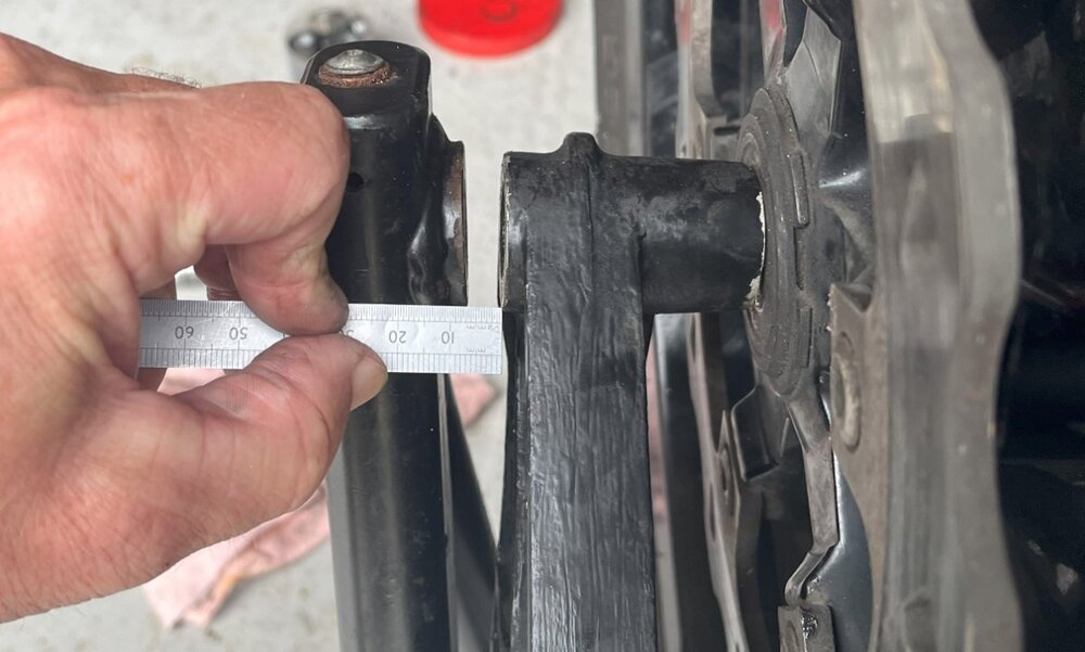
Thought I'd close this out by showing my (hopefully temporary) solution to fit the original steel swing-arm. Adding the widths of the components together, it was 6.7mm short of the designed 301mm between arms so I machined up a thick washer and milled a "T"-shaped brass block with 10mm reamed hole to take the brake calliper pin.
-
The Moderator has very helpfully checked and given me the links to the manuals that didn't seem to work from the threads I found that gave them on this site. He says they work now. This shows the forks as being the FG43. Interestingly, I contacted Brooks of Bradford, a specialist Ohlins repair and refurbishment specialist here in the UK that refurbished and replated my front forks 4 years ago. (They have worked brilliantly ever since without any oil leaks in probably 15-20kmiles, something that was giving me a problem before in spite of changing the seals). I asked them if they had any record of what model they thought the forks were and got the answer FG313. I got the manual for this as well and there does not appear much difference between the two. The only thing I noticed was that the compression damping adjustment in both shows the 3mm Allen key at right angles to the bottom of the fork while my adjustment is much nearer 30 degrees to the axis of the fork, with the Allen key angled upwards, as shown in the MG owners manual. They said that Ohlins often made non-standard forks for particular bikes that, while based on one of their standard designs, often incorporated differences and I guess in the V11 case this meant a different casting at the bottom of the fork to incorporate the brake calliper attachment. This probably explains the difference in the angle of the compression adjustment.
-
I seem to have confirmed the mistake in the Moto Guzzi manual regarding rebound and compression damping adjustment by the simple expedient of fully closing off the top-fork adjuster and then the bottom fork adjuster. It is really obvious that the bottom fork adjuster is the one that adjusts compression damping since you get a very hard response when you suddenly push down hard on the handlebars. Fully closing the rebound damper at the top of the fork is less obvious as the rebound is just damped, whereas fully opening it there is a marked overshoot as the forks come up after being compressed. So the MG manual is wrong and this does line up with the FG43 Ohlins manual. This still leaves the question as to whether the Ohlins forks fitted are based on the FG43. Unless my search skills are defective I don't seem to find much in this excellent forum on damping adjustment. There is some on sag adjustment but not, it appears, on damping. Please correct me if I'm wrong on this. I have been looking at the Dave Moss Tuning Youtube videos and reading round on the subject and it would appear that the problem I've got in navigating a series of S-bends near my home that are a bit bumpy where my line gets thrown out, is more likely caused by having too much rebound damping. This causes the front wheel to deload after bump compression, allowing it to slide sideways and definitely giving a less precise feel and loss of confidence to the rider. I will experiment and report back once the weather has warmed up. We are in a blast of arctic air for the next few days here in the UK.
-
I have a 2005 V11 with the Ohlins suspension and I wish to play around with the damping to improve cornering on bumpy roads that I find is not as good as my other bike. Firstly, does anyone know what the Ohlins fork model was (was it the FG43?) or if not, where I can get the right Ohlins technical manual on-line? (The link for this item in the V11 forum that gives links to the manuals (fork, rear and steering damper) does not now seem to work). I do have the FG43 manual as a PDF file and when I replaced the oil, it looked to be the right one. This says that the damping at the top of the forks has a total travel of 20 clicks but when I check my actual forks it is 32; hence my worry that i've not really identified the right Ohlins manual for them. It does not say in the Moto Guzzi manual what the model the forks are, only that both compression and rebound are set 13 clicks away from fully (clockwise) closed. Also, if the forks are FG43, then the Ohlins manual says rebound is adjusted at the top of the fork and compression at the bottom but my MG owners manual says exactly the opposite. Which is right?
-
Rear axle build-up and dimensions of components between swing-arm
PeterT replied to PeterT's topic in Technical Topics
That's what I like about this membership forum; there are always people willing to provide good advice. Many thanks for all your helpful replies. -
Rear axle build-up and dimensions of components between swing-arm
PeterT replied to PeterT's topic in Technical Topics
Thanks for this. You seem to have confirmed my suspicion and solved the mystery of the missing millimetres! -
The next time a member removes the rear wheel of their V11, I would be very pleased if they could measure and post the axial widths/dimensions of the 4 main components that go in-between the arms of the swing-arm. In order of assembly, from right to left, the bevel transmission, the small spacer collar, the wheel and the cast brake calliper bracket. Is there anything else? The reason I am asking this is that I have a 6.5mm (just over 1/4") gap between the inside of the swing-arm and the brake calliper bracket once the wheel and transmission are pushed to the right. For the last 10 years the bike has run with a bespoke alloy swing-arm and when refitting the wheel, the brake calliper bracket has been a perfect push fit into the gap between the swing-arm and the left hand wheel bearing. I have now tried to fit the original steel swing-arm and found this gap that I believe is too big to simply squeeze the swing-arms by tightening up the axle bolt. Someone please tell me if I'm wrong on this and if such a gap is normal. I have measured the original steel swing-arm and the dimensions seem to be in line with the dimensional specification given in the technical manual, namely 301mm between the inside faces of the swing-arms. My suspicion is that the alloy swing-arm (that I no longer have) had a slightly smaller dimension and that the brake calliper bracket was reduced in width; hence my request for someone to measure this and, in case this is no different, the other components as well, though I really cannot see how these can have been changed from the original design specification. If the brake calliper bracket has been modified, then at least I will know that, if I bought a new replacement, that this would solve my problem. The dimensions I have measured are:- Bevel transmission gear - 90.06mm (3.54") Spacer collar - 12.4mm (0.488") Wheel (across bearings)- 141.8mm (5.58") Brake calliper bracket - 50.45mm (1.99") Total 294.7mm Dimension between swing-arms- 301mm Gap - 6.3mm
-
Share your lithium battery experience; cold environment, durability, else?
PeterT replied to p6x's topic in Technical Topics
I've been running a BC LiFePO4 battery in my V11 for the last 7 years. It is 1 size smaller than BC recommend for a V11 (mine is a BCTZ14S-FP-S 12V, 54Wh) but I needed this size to fit in the Ghezzi Brian tail. It is incredibly light. It puts out loads of cranking amps. I measured it using special resistive shunt and an oscilloscope, and the initial peak current was nearly 500A before it rapidly subsided as the engine cranked over. Yes they do seem to put out less current when cold so I agree with previous comments. But they do keep their charge remarkably better than a lead type, assuming there is little or no small leakage current to drain them. One thing to bear in mind is that their capacity is not as large (they are, after all a fraction of the weight and about half to 1/3rd of the volume). The 12V, 54Whr of the LiFePO4 battery corresponds to 4.5 Ampere-hours, while the original equipment lead battery fitted is 13Ah. This is really only required to make the lead battery big enough to reduce its internal resistance so it can give enough cranking amps. The LiFePO4 battery can do this from a much smaller size because it has a fundamentally much smaller internal resistance. Obviously, you don't need much capacity to start, so the smaller capacity is fine, but if anything does drain the battery while it is not charging (like leaving the parking lights on when parked or if your charging circuit has a fault) the battery will become flat about 3 times quicker. I have a voltmeter fitted to the dashboard so I can see exactly when it is charging as I have had overheating problems with the small 30A charging mini fuse holder but I have cured this by putting in a new, much larger, Maxi fuse-holder on a dedicated flying lead that is capable of taking 100A fuses: obviously I still only put in a 30A fuse but it has cured the tendency for the charging circuit to fail due to degradation of the fuse holder contacts. This brings me to my last point which is that when I put the bike on its intelligent charger its self diagnostic does not like the leakage current the bike takes and it says the battery is faulty. This is due to leakage current through the diodes of the alternator rectifier (I think more modern bike rectifiers have diodes with much lower leakage current), so I remove the 30A fuse to isolate it and all is well. This would seem to me to be a good precaution if you use a LiFePO4 battery if it is being laid up for any time, whether you put it on the a maintenance charger or not. In fact, for a standard V11 the rectifier is probably the only significant current drain and once this is removed, the LiFePO4 battery seems to maintain charge almost indefinitely. -
The selector spring in my 2005 manufactured V11 failed after only 21000 miles. The Piaggio dealers that I managed to limp to in 2nd gear (I think) couldn't get a replacement spring quickly so I got one from Gutzibits in the UK. So I'm not sure if this was better, worse or the same as the standard part. Since this is my one and only mechanical breakdown in what is now 45000miles of happy riding, I have followed this thread with interest. Understandably, after a further 27000 miles since the last spring failure, I am concerned that it is due to fail again, possibly when touring abroad; I'm going to the Picos in Spain at the end of next month. Can anyone help me by letting me know how I can get hold/buy of one of these superior springs? I am in the UK.
-
ANSWERED OMRON G8HE-1C7T-R-DC12 DC12V or Equivalent (CIT A11CSQ12VDC1.5R?)
PeterT replied to p6x's topic in Technical Topics
I've had my share of problems with the starter motor but I've never had any problems with my micro relays. That's not to say that the starter contactor may not draw a short-term current that could cause problems, it's just not something I've experienced (yet). However, I have experienced exactly the same symptoms; lights dim when starter button pressed and you hear the click of the starter contactor but it doesn't crank, or ties to so weakly that you know it's not going to start. You try again and sometimes it may work, sometimes not. The cause in my case (and this is the reason I thought I'd add to the wisdom already given) was that the crimped (female) blade that pushes onto the starter motor contactor, was not particularly strong/grippy and had a bit of corrosion in it. Sorting this out cured the problem. Effectively insufficient current could be drawn by the contactor coil to pull in the starter contacts strongly enough, these then added extra resistance to the starter motor circuit and the motor cranked weakly or not at all. Perhaps it was this that caused the actual starter motor contacts to arc and pit, because soon after this I had the same thing again, but this time diagnosed that it was these main contacts that take up to 500A peak and typically interrupt the 120- 150A d.c. cranking current in an inductive circuit. This in itself is something that you might expect to cause degradation over time. Anyway, having checked that it wasn't the same thing again and diagnosed that the actual main contacts were adding abnormal contact resistance, I fitted a new starter and this solved the problem. So my contribution in all this talk of getting better relays (and of course the relay could also cause a weak pull-in of the starter motor contactor relay) is to make sure you have checked these other two causes. -
I had a similar problem on my 2005 V11 but I didn't think about the possibility that the volts may be dropped across degraded contacts of the ignition switch that feeds the contacts of the starter mini-relay and through that the starter contactor coil. So I'm definitely NOT saying that any of the previous conversation and ideas are wrong. Quite the opposite. Putting a voltmeter on the input to the starter motor contactor would show whether this is the problem, especially if you know what the normal voltage drop should be. My, hopefully positive, contribution to this thread is to say that my diagnosis was that there was a problem with the starter motor contactor whose contacts seemed to add sufficient resistance to make cranking poor or to stall. It was never clear to me whether the mechanical contactor mechanism degraded and was getting partially seized so as to put less contact pressure on its starter contacts, or if it was simply that the starter contacts themselves had started to pit and degrade. All I noticed was that the starter motor was very slow (or would fail to crank) but often would start OK on the second attempt. My hypothesis was that this was either because the battery was a bit warmer and delivered a bit more current to the contactor coil or perhaps the main contactor contacts just closed with a bit less contact resistance that time. I got a new starter and the problem was solved, so, in my case at least, I feel that the problem was a degradation in the motor contactor mechanism or contacts. At 500A transient peak and 150A cranking, just the slightest extra contact resistance can be disastrous and with this d.c. current you might expect contactor deterioration over time. But the possibility that the contactor coil does not get sufficient current to pull in the main motor contacts strongly would have exactly the same effect so worth bearing both in mind before investing in a new starter.
-
I've tried a few different tyres on my V11 and carefully logged the wear rate and experience. Starting with Metzler Sportec M5 that felt a bit less grippy in the damp and wet and would feel "squemish" when traversing painted while line in the wet. They only lasted 4k miles. I then tried Metzler Sportec M7RR; the latest version at the time. They felt a bit better in the wet and the life was about the same; around 3.5 to 4,5k miles with slightly more life for the front than the rear, although I always change both at the same time to keep them in step and avoid having to spend even more time going to the tyre shop. I then tried Pirelli Rosso III's. They were even better than the Metzler in the wet and lasted a bit longer too; 5k at the rear and, potentially 6k on the front. I then tried Pirelli Rosso Corsa II's and they were a bit better still in the wet and possibly wear very slightly better as I got 5.5k out of the last pair (though this might be that I'm getting smoother or slower) and I've fitted these the last three times.
-
Thanks, I thought the Ohlins documentation was more likely to be correct but I thought someone would know for sure. Just worth checking before I start "fiddling" with the settings.
-
I've just changed the fork oil on my V11 with the Ohlins suspension myself after having the forks professionally restored some 12000 miles ago. (They were giving me oil leak problems and the mechanic saw some minor corrosion/pitting that he thought might be responsible for new seals not curing the problem. Since getting them professionally recoated and nitrided I have had no problems. The company I used was Brookes Suspension in Leeds, UK) In looking for information prior to changing the fork oil I looked at various sources of information and in doing so I saw what appears to be a mistake in the Guzzi Owners manual or the Ohlins documentation. The Guzzi manual says that the Allen key adjustment at the top of the forks is for compression damping and the Allen key adjustment at the bottom is for rebound damping. However, I also found on the internet, an Ohlins PDF document for the FG43 fork for the Moto Guzzi Scura (that I'm assuming is the same as my 2005 Cafe Sport) that very clearly shows the top adjuster is for rebound and the bottom for compression damping. Which is right or have I picked up the wrong Ohlins documentation? Having partially dismantled the forks I am tempted to try experimenting with adjusting them and perhaps re-setting them up since I am on the "lighter than average" side and my Ghezi-Brian conversion took 30kgs off the weight; hence my interest in clearly understanding what does what before I start. Can anyone clear up this confusion?
-
1st real ride, 1st breakdown. Battery drained
PeterT replied to bsanorton's topic in Technical Topics
Apart from the 30A charging fuse and fuse-holder that you have been advised to check, the other place to look is the plastic 4-wire connector (two +ve and two black) that the alternator regulator are plugged into that takes the power to the fuses at the rear of the bike. Mine is cable-tied onto the front frame just inside and at the front-left of the fuel tank. Because it is 4x 15A/connection, it isn't of the sealed AMP type but a less sealed connector, and, as a result, can get wet and corroded if it isn't well protected by Vaseline or anti-corrosion grease. Having parallel connectors and wires is also a fundamentally poor bit of electrical design since if any one connector goes high resistance, all 30 A can go through one 15A wire, overheat it, and potentially damage other wires in the wiring loom. -
Rear drive needle bearing and swing arm restoration
PeterT replied to Bjorn's topic in Technical Topics
I found this thread v. useful since I too found my small, outer, unsealed needle cage all rusted up just like the pictures shown. Greasing it at every tyre change is a "must" from now on! So armed with this info I bought myself a slide hammer bearing puller (only £35 from Amazon), a new needle bearing and inner race and a canister of freeze release. I did try "wacking" the back of the bearing to drive it out from the other side using a thick steel rod before I realised that I was just hitting a thick steel washer that the bearing is squashed against that appears to be trapped in by a steel cylinder that lines the surface into which the bearing is inserted So at this point I looked at this thread and got myself properly prepared. I levered out the inner cage and needles with a screwdriver to give me a surface to pull against. I heated up the bevel box first by just setting it close to domestic room heating electric fan. The bevel box was still filled with oil. Using my meter that has a thermocouple and a setting to read its temperature, this showed that I got the whole box to about 45-50deg.C. I then inserted my 30mm puller and expanded it to catch the outer lip of the bearing and I squirted some of the freeze/light oil release (though I'm not really convinced that this actually did anything). I then spent about 10-15 minutes playing my hot-air gun around the needle bearing, monitoring the surface temperature until it got up to 100deg.C, and then used the slide hammer. It did pull the bearing up about 4mm before the outer lip distorted, expanding just enough to allow the puller to detach. Now that there was a gap at the back I then re-seated it against the back face, tightened it up, gave it another freeze spray and reheated it back up to 100deg.C and then with about 5 or 6 modest slide-hammer wacks it came out. I am now just carefully contemplating how I can pull in the new bearing with a bolt down the central axle hole after, heating it up to what appears to be an obligatory 100deg.C. Any good thoughts or things I should be careful of here? -
Thanks for some good suggestions that I'm sure will be helpful to me and any others who have this specific problem. Thanks
-
Yesterday I looked on this excellent forum for any ideas that may explain poor cranking and starter performance that rather suddenly appeared when I tried starting in the morning after a fairly cold night (around 6deg.C 43F) a few weeks ago. I first assumed that, after 5 seasons my LiPO battery was starting to age and with the cold and higher oil viscosity that this was the problem so I bought a new battery. The effect seemed to be temperature related; always being a problem when cold starting. The new battery didn't cure the problem; hence my looking at the forum. There didn't seem to be a dedicated topic focused on exactly this problem, hence this new specific topic, but by various searches i did find a few ideas, even one that reported a similar problem because they had put in 20W-40 oil rather than the recommended 5W-40 oil and this became a problem on a cold day. In fact I made a list of all the possible options and there are lots, (battery, starter, starter contactor, connections etc. including the possibility of the magnets becoming demagnetised (on a Ferrari forum), but obviously the most likely was a poor connection so I stripped down all the connections between battery and starter, including the heavy duty earth cable that fixes to the gearbox casing, cleaned them, added corrosion protective grease and reattached but really didn't see anything that gave me the slightest concern. However, on dismantling I did take off the insulated spade terminal that supplies the voltage to the starter contactor and it didn't feel a tight push-on. I used pliers to compress the jaws of the female insulated terminal, cleaned up the spade that emerges from the starter contactor next to the large +ve starter terminal and reattached. Problem solved! Obviously high resistance to the contactor coil can cause the contactor to pull in rather weakly, leading to high resistance in the main starter contacts and a weak start. I am putting this experience out just in case anyone has a similar problem. It might be useful for others to add their own experiences associated with solving the problem of the starter motor working but having difficulty in cranking the engine as quickly as normal.
-
I've had a a Lithium Iron battery fitted for 5 seasons and it has not needed any change to the regulator at all. In fact I have a voltmeter fitted. The battery starts at about 13.2V with the 6A pre-starting load. Once it starts the voltage slowly rises as the generator recharges the battery from the starting load and the regulator gets it up to about 13.9-14V max which the makers say is perfect. I got it fitted by Ghezzi Brian in Italy and this was the battery they recommended. I'm sure they have lots of experience with these. BC battery BCTZ14S-FP-S.BC do a range. I got it on e-bay for just over £110. This is the second to largest LiFe battery BC make for bikes and specifically for starting. I think they recommend the largest one for a V11, but with the Ghezzi Brian tail mod I have this is the one that fits so it's all credit to the battery that it has lasted longer than any lead acid I ever had. It is fantastically light. I measured the peak transient cranking current and it peaked at just under 500A! before it subsided as the motor cranked the engine to a fluctuating 150-200A. I do put a LiFe Optimiser battery charger/health monitor on it over the winter although if disconnected these batteries keep their charge better than lead-acid. One other bit of experience is that they don't like low temperatures. Below 10deg.C; the internal resistance goes up and becomes noticeable in reducing the initial starting current. However, if it is a cold morning start, then the current does start to warm it and everything is OK. You can either let the lights load warm it a bit first or just start it - you just get a weak initial start when you first push the button but this load warms the internals. Above 10deg.C you are unaware of anything different and the bigger battery they recommend will almost certainly make this effect significantly smaller.
-
The best way of thinking about what is happening is to think of the way you would arrange for a relay to latch itself ON and not turn off. The way this is achieved is to connect up the contacts so that if you energise the coil, it switches connects a live (12V) feed to the side of the coil being energised. So, when the initial coil energisation is removed, the relay stays energised directly from the battery. This is what is happening on the V11. The lights are connected directly to the battery; they don't go through the ignition switch but, if everything works correctly, the ignition switch energises the lights relay and this switches on the lights and off when the ignition is switched off. What is happening is that a short circuit between this circuit and the output of the ignition switch is keeping the lights ON AND energising the output of the ignition switch and keeping the engine running. In effect it is just like the simple latching relay circuit. And the only way to switch it off is to interrupt the coil current which pulling in the clutch and pressing the starter button does. In fact, if I'm right, you don't need the tank and to start and run the engine to get this effect. Just switch on the ignition. The lights will come on but if you switch off the ignition, the lights will stay on. Assuming this happens, I think you can be confident it is a short between the red/black wire and the Orange/blue wire that is causing the problem. Now, your comment that if you disconnect the 5-way everything works OK is also interesting. The red/black wire goes through pin 4, but the Orange/Blue wire that goes to contact 3 of the ignition switch does not. However, if if you have the side-stand down, the Orange/Blue wire could be falsely energised if there was a short-circuit between the red/Black and the white wire that goes between the Neutral gear relay and the 5-way connector and this also connects to the White/brown of pin 2 of the 5-way if the run-stop switch is closed. This would imply that the fault between these two wires is not in the long harness down the spine of the bike to the relays in the rear but in the wiring and switches of the RH handlebar controls, either in the 5-way connector, the wiring or the control switches themselves. This is good news. Can you put a meter across the various pins in the 5-way connector when it is disconnected? I'd specifically look to see what pin 4 (Red/black) seems to be connected to. It should connect to pin 5 if you collapse the side-stand, but should not connect to any of the other 3 wires. My expectation is that you will find a spurious connection between the red/black on pin 4 and the adjacent White/ Brown of pin 2 or possibly the white wire of pin 1 that are connected together by putting the kill switch into the RUN position. If so you then need to work out if the problem is a fault in the RH handlebar switches, in the connector or the wiring between them.
-
OK. This I can understand. Fuses 6 and 7 power the parking lights and direction indicators and are turned on by the ignition switch that feeds them from contact 2 on the ignition switch. So, when you turn off the ignition switch, they should stop working. What has confused us is that the rest keeps working. But this is understandable because it is only the wiring from contact 3 of the ignition switch that is being kept on by the fault short-circuit between the Red/Black wire coming from the Lights mini-relay. Since this is fed directly from the battery via Fuse 4, it doesn't go through the ignition switch, and so this fault can keep this circuit working until you pull in the clutch and press the starter. At this point it de-energises the lights relay and interrupts this faulty supply. So this is all consistent with there being a fault between the red/black wire from the lights relay and the Orange/blue wire from the ignition switch that goes to the starter and the Neutral Gear mini-relays as well as to the front dashboard 12-way Amp connector to power the neutral lamp. So i really think we have it nailed. Disconnect the ends of these wires at the relays, ignition switch, side-stand switch and 12-way connector. Test between them to prove they are shorted. If they are then run new wires, sleeve them, replace the terminals and reconnect and tie them neatly in parallel with the harness to take their place. Let me know how you get on.


