
motoguzznix
-
Posts
283 -
Joined
-
Last visited
-
Days Won
4
Content Type
Profiles
Forums
Events
Gallery
Community Map
Everything posted by motoguzznix
-
you are right concerning old threads Since the early days of the "open the cans" thread I modified another V11s exhaust cans in the same way. This bike responded even better than my own V11 on the modification. Additionnally I took some photo shoots during the work. This convinced me to post the results again. The gains are not so small: 3 RWHP on my bike and 4.5 HP for the second bike. And you can feel the difference while driving, it's not just dyno figures. 90 % of the aftermarkeet cans that are fitted to the V11s around do not show any bigger gains without A/F ratio changes. But my modified cans did also benefit from mapping changes: Torque climbed from 8.8 to 9.5 mkg, max power was about the same but the gains between 5k to 8k were up to 6HP. When I fitted open Leovinci cans, neither max power nor torque was any better, only the torque minimum at 4000 was slightly up from 7 mkg to 7.5. But you still have the heavy stock cans. It depends on you if you like the looks or not. The modifications are unvisible from outside as all the welding seams are underneath the oval light alloy covers. There is everything written on the cans an officer likes to see and they will never arouse suspicion as they are only marginally louder than stock - slightly deeper tone and even at high rpms just a bit louder. That's because the complete volume of the cans is still used for noise reduction while flow resitance is reduced a lot. And weight helps reducing noise. There is only one disadvantage: you can't bye it cheap on ebay. You have to du some work yourself. Not everyone is able to do this and not everybody would like it. But for those who can and like to spend the 2 - 3 hours of time there are good gains for your .
-
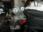
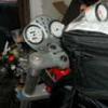
Here the description of my modifications taken from the "unpacking the cans" thread. There are also some power and A/F measurements included. My mods: The idea was to let the gassses pass the muffler without changing the direction. Originally, the gas enters through to to chamber 3, turns back to 2, 1 and back out via the very long end tube. In the first chamber I cut' out 50 mm from the tube which enters from the collector. (On the mufflers I modified, there was the catalytic converter in that place). The 2nd chamber remained untouched. In the 3rd chamber I cut' out 50 mm from the upper tube which goes out. The 4th chamber with the steel wool remained untouched too. So the exhaust gas flow finds an open end in chamber 1, passes to chamber 2, 3 and can leave from there via the much shorter end tube. No change in direction. The changes can be seen in the upper schetch below: The modifications are easy to perform, see some pictures taken during the work: I cut' a window in the 3rd chamber from front the end tube will be removed from there The front cap will be sawed off just behind the welding the end piece of the end tube will be cut' off, from the thick lower tube where the gas enters must be cut out by 2-3 inches The power comparison on my own bike - the upper two curves show the influence of the exhaust mods, no other changes. Power graph On an other bike the gains were even bigger: The two lower curves show the influence of the mods on the same bike with stock mapping - the 3rd upper graph is a bike with additionnal mapping changes and a different exhaust. Sorry for the low quality of the picture - the scan wasn't better. These mods are easy to perform - it took me about two hours for the second pair of mufflers. Welding the mufflers is most time consuming - depends on your practice.
-
You have now an engine that is assembled with different parts than it was before. So you might have a different CR than stock or some other changes. First I would go through the usual tuning procedure: Adjust TPS, synch the Throttle bodys, adjust idle, set the CO trim in the ECU to 3,5 % CO at idle speed. Spend a set of new spark plugs. I bet my this will cure your symptoms. If not, go further: Fuel pressure is regulated by the valve situated on the fuel tank where the return line is connected. If your Kawa pump is able to deliver enough fuel pressure, the valve will reduce that to the requiered figure. Connecting a pressure measurement device is a good idea. Fuel pressure is 3 bar on the V11, 1100 Sport should be the same, could anybody take a look into the worksop manual to doublecheck that? Good luck Ernst
-
Hello Sorry for the low quality of my pictures. I hope you can get some impressions fron the cans. If you are interested, I can add some pics from my can modification that support the writeup in the "open the cans" thread. The mods are quite simple if you are able to handle a saw and a welding device. Ernst
-
Hi Bob I did You have to remove the silver coating first (mine were silver) which adheres very good. So this was a sweaty job. Then treat the cans with wet sanding paper beginning with 150 and up to 800 - 1200. The finish has to be done with a polishing disk and wax. Then the cans are really shiny and you are as dirty as you ever can be. I also polished the headers and the crossover. Looks really fine. Especially these are much better to keep clean when polished. I also modified the cans for better flow. The mods are described in the "open the stock cans" thread that can be found with a little search.
-
I would check the temperature sensor in the head: If the reading is too low, the ECU will enrichen the mixture. You will find a lot of info regarding the subject when searching.
-
Desdinova The fuel trim should be adjusted with a COmeter in place - around 3.5 % on a bike without catalyst works fine. Just zeroing it cannot be the right solution as you don't know where the figure really is. Adjusting the trim +-3 makes a substantial difference in the CO reading. With the CO adjusted correctly there may be no need for the PC to make the bike running fine. Normally a PC map works correctly in a properly tuned engine. Setting the trim so far from zero to get it running shows how far from the truth the map really is. I would not bother with it for any longer. Look for a proper map for your bike - there are sources in the forum to get the right one.
-
Congratulations to your "new" toy. Mine is a 2000 in black, so identical. 150 mV ist the base adjustment: disconnect the linkage, close the throttle, unscrew the right stop screw until the actuation cam is free and make sure the high idle lever is backed off too. Unscrew it if necessary. Let the throttle snap back sometimes until you are in the real closed position. Then adjust the 150 mV taken from the TPS connector. Next step is adjusting the right idle stop screw to 500 - 525 mV. Close the bypass screws on both throttle bodys. Reconnect the rod, start the engine and synch the idle. So the 500 mV is the TPS voltage at idle speed. But it is only the correct throttle position if the first adjustment is done correctly too. The injection has an air pressure sensor inside the black box that compensates for the altitude. No need for taking this into account when adjustng the TPS.
-
I agree that the unsufficient broken in engine is the reason for the failure. My own V11 felt much better after approx 3000 km of running in. I did not stick in the lowest rpms but I did not ask more from the engine as he wanted to give with ease. When a motorcycle has only 1700 km since 1997, then there were very long periods where the engine had not been running. During such a long period, the oil drops off from everything where it is normally adheres. So the following cold start is performed under the worst circumstances concerning the oil supply. This combined with hard riding of a not broken in engine may lead to such a failure. Concerning the blocks: The Cali block has an rpm sensor on the right side of the clutch housing. This is not necessary for the 1100 S as there is only a trigger wheel behind the camshaft sprocket. Plug this hole, all the other parts of the V11 engine including the clutch should fit into the Cali block. Also the camshaft with the trigger wheel, as the Cali block has the TDC sensor in that place. If you have the choice, put the Mike Rich pistons in the engine. CR does climb substancially too and the piston crown has a much better shape to cope with the combustion chamber in the head. Chamber shape with the fbf pistons is worse and CR seems to reach unhealthy figures in some occasions. But when putting in high CR pistons, camshaft and intake ports are the key to real torque in the V11 engine.
-
Desdinova some suggestions: Check first the voltage across the battery - also when you try to start with the gear inserted. Maybe there is a short in the circuit that lowers the voltage when the side stand is up and the gear in. Are you sure the ECU and coil/injectors get enough volts to work properly? Both are actuated via two relays and these should be checked first. The relays get the voltage from fuse F1 and F2 - check if tension is lost in the relays. As some people prior to me supposed: if the idle speed is that high, maybe air can intrude into the intake system . My last suggestion: An exhaust valve or seat may had cracked. Perform a compression test or better: set the piston on closed valve TDC (as for valve gap checking), connect the compressor (0,5 - 1 bar) via the spark plug hole to the compression chamber. Pull the exhaust tubes and listen to a whistling noise. If the valves leak you can detect it easily.
-
Not correct Valve clearence ist not measured at the lobe but on the basic circle of the cam. So even the lobe is worn severely the clearence might be unaffected. But checking the piston is worth the effort. If the cylinder is dismounted, pull the cam followers too and check the cam below. Usually the right exhaust valve is the first to wear. The slightest flat or edge on the lobes makes the cam ready for the scrapeyard. In that case, I would opt for an aftermarket replacement as there are a lot of good choices available: In Germany Dynotec, HTM, HMB In UK raceco In US megacycle In Italy Bruno Scola
-
Did you shorten the stock exhaust cans? What mods have you applied? I modified the stock cans too and got a little more power on top with very little noise increase. The mods are somewhere in the "opening the stock cans" thread.
-
The V11 has unlike other Guzzis no relay installed for the signal horns. So I would install one as the switch gear will not cope for a very long time with the 12 A a pair of these horns are pulling from the battery.
-
There is no need for a liquid sealer in this place. These parts are fixed with left/right threaded nuts and sealed by a ring seal made of plastic material. There is no need to seal the threads as the ring gasket seals the connection. Fuel petcocks on earlier carb Guzzis were fixed the same way. They never used any sealing compound at this place.
-
Be sure the weldig will not last for long and crack again. HTM in Germany sells the headers for 150 € (without interference tube).
-
Some years ago there was a thread about battery current sucked up by the ECU. Some WM1.5 ECUS do this, others don't. If your bike falls into this range, pulling fuse #1 prevents this. I always pull this fuse when the bike sits for longer than a week. After 4-6 weeks, my battery is empty and fails to start the bike. I'm sure this effect can distroy the battery if it occurs during the complete winter season.
-
Maybe the idle mixture is too rich. Try setting the idle trim to get 3,5 % CO.
-
voltage regulator malfunction
motoguzznix replied to Slavomir Musilek (R.I.P.)'s topic in Technical Topics
Slavomir In Germany, at "Bike affairs" in Bredenbeck, there is a voltage regulator available at € 82.- This works very well and is applicable on every bike with 2 yellow cables coming out of the alternator. You just need to crimp on some connectors - it is not plug and play as the stock regulator is. I used it successfully in a Guzzi Quota and a KTM and should the regulator in my V11 fail I will use it again. Additionally there is a little trim screw on this regulator to fine tune the max tension of the alternator. -
Tom The 520 mV setting is for the earlier bikes KR and KS. Later bikes should have 460 mV and you are pretty close to this. I agree not to change the 150 mV closed setting. Setting your valves to 0,008/0,010 might lower the idle speed slightly that you can raise the throttle setting to 460 mV. This should prevent the coughing.
-
I do not see big problems to double the V11 side stand circuit into a 1100 Sport. I did this once for a Centauro and it works well. Only installing the switch that interrupts the ignition is not favorable as the engine does not run with the side stand down. HMB in Germany sells side stand kits for the the v11 including the switch. Additionally you have to install a relay that supplies the ignition if activated. The relay will either be activated by the side stand switch if its pressed (sidestand down) or by the burnig neutral light. One change has to be made in the dashboard as the +supply for the neutral light has to come from the Ignition+, not from the + supply of the dashboard as standard. I installed the relay underneath the fuel tank where I cut the white + supply to the kill switch and connected it directly to the relay input. Details can be taken from the V11 wiring diagram. This makes the switch perfect working like on every Jap bike: The engine runs with the sidestand down, if you touch the gear lever to insert a gear the engine stalls. And all done without electronics, just with a relay installed.
-
David Thank you for quoting my post again - I can assure you I was not one of the 5 Guzzi experts....
-
I own a LM2 for 25 years and tried a lot with it. The stock cans cost power and torque low down. The engine comes into its own between 4 and 5000 rpm which is not a desirable character. The Lafranconi competiziones perform much better with good grunt low down. The sound is the best you can have on any Guzzi! Forget fully open V11s or Ducs. But it is really loud, not everybody likes that. I used up 3 pairs until the rust holes were too big to weld. Now I mounted the complete LM3 System headers/crossover/cans and I'm very happy with it. A fine Guzzi sound but not too noisy. Power is not limited until the engine goes over 90 HP. And they do not rust! If these are too smooth, Lafranconi sells competiziones for the LM3 too.
-
Raz I disassebled a lot of guzzi clutches and the intermediate steel plate was warped on almost every clutch. With very low mileage you might have the chance to find an unwarped plate. This makes the clutch engaging point unstable and eventially the clutch fails to disengage. I did this mod on my own V11, but only 7000 km since then. No problems, but this in not really a durability statement.
-
Raz Guzzi quotes 8 mm thickness for a new plate and 7.5 for a worn one. But when I measured new plates, the starting figure was mostly at 7.7 to 7.8 mm. And I disassembled perfect working clutches with friction plate thickness near 7mm. There is an opportunity to drill and saw in the new steel plate to prevent the new one from warping. Drill 6 holes of ~3 mm into the steel plate in 60° distance in the middle of the friction area. Saw in the plate from the outside to the first hole , the next from the inside etc. There is a description of this modification somewhere in the net, but I can't remember where.
-
This is qouted at 1,5 mm measuring play. My own measurements confirm this: In/ex 254/253° at 1,5 mm
