antmanbee
-
Posts
116 -
Joined
-
Last visited
-
Days Won
5
Content Type
Profiles
Forums
Events
Gallery
Community Map
Everything posted by antmanbee
-
It's Alive!!! Tonight I had some time after work so I went out to the bike with my laptop and ran Guzzidiag. One of the actors is injector test for L and R. I already had the inner rubber manifolds off so I had a good view of the injector tips. I tested the injectors a couple of dozen times until I had a nice puff of fuel mist from each. At first nothing had come out. I also thoroughly flushed the fuel line and bled it from the lowest point and then at the regulator until I had a steady stream. Put it all back together and it fired first time. I wont have a chance to take it out on the road till the weekend, but I will report back again. Thanks for all the great suggestions.
-
I lived about a dozen years in Thailand but I am not there now. I am still considering retiring there. I have seen Ducks and Triumphs there but not Guzzis.
-
That looks like a handy way to clean the injectors. I might try and build something similar. I didn't measure the supply, but I do have good pressure because when I go to remove the fuel line at the regulator it squirts a lot of high pressure fuel out as I remove the hose. I would like to figure out a way to fix it in situ. Maybe tapping the pin with something to free it and with some solvent.
-
Well I got my V11 all back together but it wont start. It cranks fine, fuel pump pressurizes, got spark but no fuel. If I squirt a little fuel into the manifold balance fittings, it fires. My diagnosis is stuck injectors, as the bike only has 5800 miles and has been sitting for a decade or more. The tank looked clean but was completely dry. My question is are there any tips for getting the injectors out? There are two flat head Allen head bolts that are extremely tight for each injector and I am afraid to put more torque on them. Or any way to un-stick them without removing them? Or is my diagnosis wrong?
-
Use the Guzzi diag reader to pull the map and then load it in Tuner pro and you can see everything.
-
Any pressure either outward or inward to the crankcase is handled by the hose on the top of the frame that normally goes to the airbox. I am not using an air box so I will have it go to a small breather filter so that any air that may enter the breather system is filtered. Some bikes more than others will have a tendency to form sludge which we sometimes find in the oil pan when removed for an oil change. So no matter how good a job of flushing the spine chamber, more rust is likely to form and flake off from time to time. I will be checking my other Tonti framed bikes too, to discover if any rust has accumulated. If I am not mistaken I think the lower hoses on the tonti frame go to the cylinder heads that are up higher than the frame barbs so it may not be an issue. On a Tonti/Ev/Jackal/Bassa the breather system consists of a hose from each cylinder head to frame (at lowest point of system and lower than cylinder head) and the big S/hose from the crankcase to the frame High part of frame) and the line to let it breathe from the frame (highest part) to the airbox. I suppose it is possible to have the frame fill up with oil from the cylinder head lines but I have not had much that I can recall come out when replacing the lines. I have not had issues with oil in the airbox on these, although some do. I don't think there is any return line to the sump anywhere. As usual for me I toss the airbox but leave the breather system intact except for the frame to airbox line that I connect to a small breather filter. The spine breather seems to have the most potential for putting debris into the crankcase, I don't think it is a good idea.
-
I think what I am going to do is plug the oil pan where the return line goes in an run a hose out of the bottom of the spine breather chamber and cap it, and then periodically drain it. Unless it causes excessive oil consumption I can't see how it is a good idea to return this to the sump. The top of the spine hose that went to the air filter box, I will run that line to a small breather/air fliter. The fat 3/4" S-shaped hose that goes from the underneath/front of the spine to the crankcase breathe tube on the back top of the engine will remain. It has been too much wasted time trying to find a filter that I think will flow oil for the return line. No return line means no debris or contaminants returning to the oil pan.
-
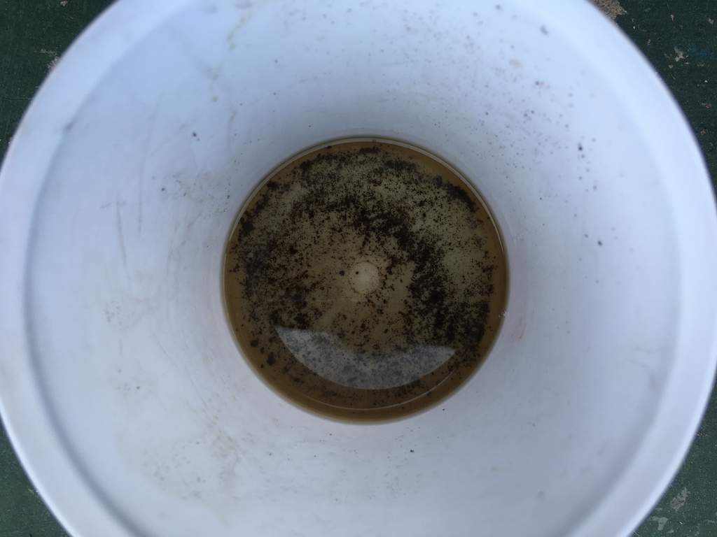
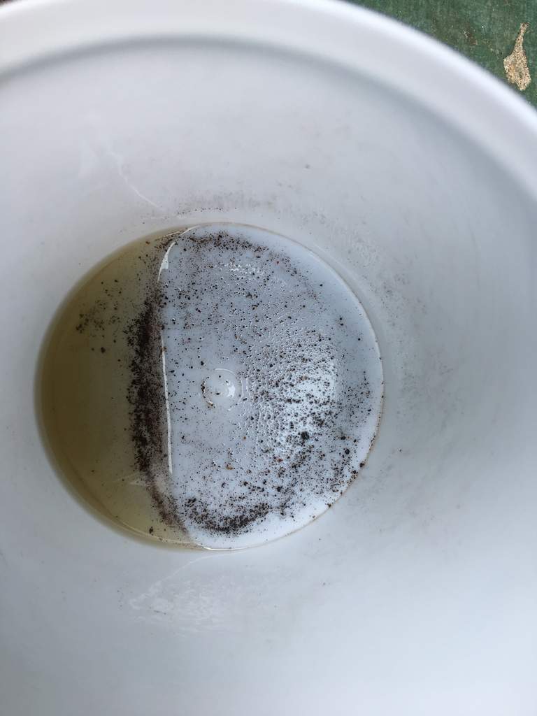
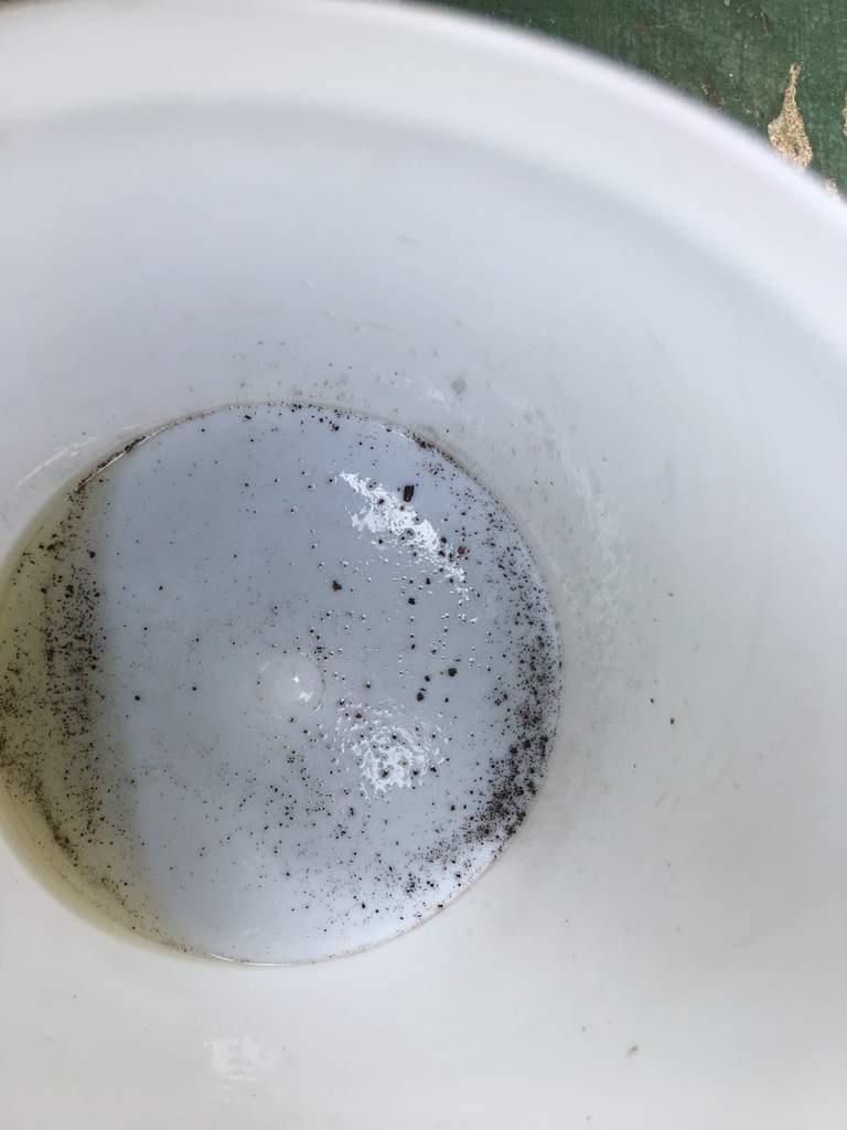
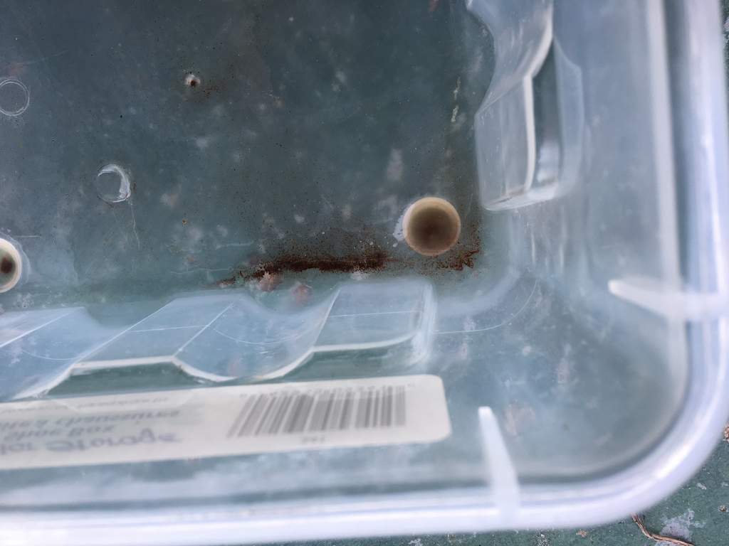
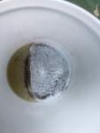
I flushed a bunch more times. All the debris looks like it is just little rust specs or flakes so I don't think it is disintegrated rod bearings. I have a feeling that probably many of the spine frame breather chambers have rust specs just like mine. I think the easiest way to check without getting as involved as I am is to just lift the back of the fuel tank and undo the banjo fitting at the lower end of the breather tank and then take a small clear hose and suck out the residue in the bottom crevice and have a look at that and also to put a little swab of cloth in a hemostat and swab out the lowest point of the chamber. That is how I got most of my debris out. It all collects in the low spot. I am think about cutting the return line and putting a small inline filter in but I don't know what filter will flow oil not under pressure. Any suggestions? Pictures are of subsequent flushes. Now they are coming out almost completely clean but there is still just a little.

-
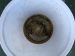
This is a picture of the first flush with gas of the spine crankcase breather chamber. It looks like only small rust particles and not the same debris that came from the oil cooler or oil pan. There was a small amount of water, maybe less than a cc or so when I used a syringe with a hose on it to suck out the very bottom of the chamber before I flushed it. Mostly oil was sucked out, maybe a couple of cc's and I squirted it onto a paper towel and it looked like no particulate matter. I am going to flush it a few more times.
-
I think he has a tonti bassa (just guessing) so the TPS is on the bottom of the throttle body on the left. I did post this hastily before I went to work and yes there is more to do such as bypass screws, idle balancing and midrange balancing after setting the TPS. I was not trying to give a complete guide as to how to do it, just to mostly point out that a number of other things need to be addressed before getting into Guzzi Diag. I would recommend reading the thread you linked as well as googling it to read several other extensive threads on this. This is a good one to read too. http://bradthebikeboy.blogspot.com/2012/10/throttle-position-sensor-setting_21.html I read and printed out about a half dozen guides/how to's before I attempted my first TPS reset/TB sync. I followed Meinolf's recommended settings for my Tonti frame 1100s.
-
I agree, git rid of the PCIII. But before you even get to Guzzidiag I would recommend doing a good basic tune. Valve adjust, Test, inspect, ohm out ignition wires, caps, etc., new plugs. New air filter, fuel filter. Remove the left end of the long throttle body linkage rod. Then set the closed throttle TPS setting with the left butterfly stop screw backed out so it is not preventing the butterfly from completely closing. I think this should be 156mV. Check with ohm meter. Then turn in the screw till you get to about 525mV. This value can vary somewhat depending on how high an idle setting you want. Make sure the engine temp sensor is making good contact. You can carefully unscrew it from the plastic housing and put a dab of copper anti seize paste on the very bottom end of the sensor to make sure it has good heat transfer from the engine. Then you can hook up Guzzi diag and set the CO trim. You may not need to mess with the maps. Some do some don't. Try it first.
-
footgoose, Thanks for the suggestions. I was thinking along the same lines. I definitely want to flush it at least a few times and inspect what comes out so I can be as sure as possible it is clear of debris. I was only going to use gas as it evaporates better and the smell goes away faster. Diesel stinks for a long time. What if I decide to park in in my living room. After all it is a work of art. docc, I also thought about a filter in the return line but oil does not flow too easily through a filter. That was why I was thinking of a catch can so I could inspect the oil collected and not return it to the crankcase. I have really no idea how much oil goes through the crank case vent system.
-
If I had it stripped down to the frame, that is exactly what I would do. I tried flushing my oil cooler probably a couple of dozen times or more with gas, air and water under pressure but debris kept coming out. I would never feel confident I got it all out. I gave up and got another oil cooler.
-
I am extremely interested in the crankcase breather reservoir clean out. I am concerned about if any debris made it into the frame that is part of the breather system from when my engine self destructed. I seem to recall a post from someone discussing about how debris that was possibly from the breather chamber ruined a second engine. It looks like the return oil hose that connects to the spine about half way down underneath may be the lowest point of the chamber. The frame just a little bit further down from that hose connection looks to have a plate welded inside the frame to keep oil from running all the way down and filling up the frame. Just the top one foot of the spine is the breather box. I really am not sure how to go about flushing the frame. Is it just an empty chamber or is something inside it? I think I may be able to pour some gasoline in there from the fitting on the top of the frame. I will plug the 3/4" main crankcase breather hose fitting that under the top part of the main frame tube and the fitting on the bottom left that goes to the back of the oil pan and let the gas soak and slosh around for a while and drain from the bottom hole and see what comes out. I have considered plugging the fitting on the back of the oil pan and just running the hose from the lower frame fitting to a catch can. That way I don't need to worry about any debris going back to the pan. Any Ideas?
-
https://www.ducati.ms/forums/92-hypermotard/132039-ran-out-fuel-twice-no-fuel-light-3.html For those with an internal fuel pump this may be the best solution. Full instructions and pictures. Look at posts #23, 30, 41, 42. I just ordered 3 from here, https://www.digikey.com/product-detail/en/honeywell-sensing-and-productivity-solutions/135-202FAG-J01/480-3340-ND/2503925 I am going to try this for my Breva 750 with an internal pump similar to the Ducati and later Guzzi V11s. My light comes on when I first turn on the key but will not light when the fuel is low. I have run out twice on this bike when I first got it and did not know I had an issue.
-
Interestingly the 2 bottom bolt holes for the rear main bearing on the replacement engine are blind holes. No opening to the crankcase. On the original trashed engine they go all the way through. The bike is listed as a 2003 but was manufactured in 2002. Engine has crackle paint. The replacement engine is a 2003 (no crackle paint). So only 6 possible leak points not 7 on this engine!
-
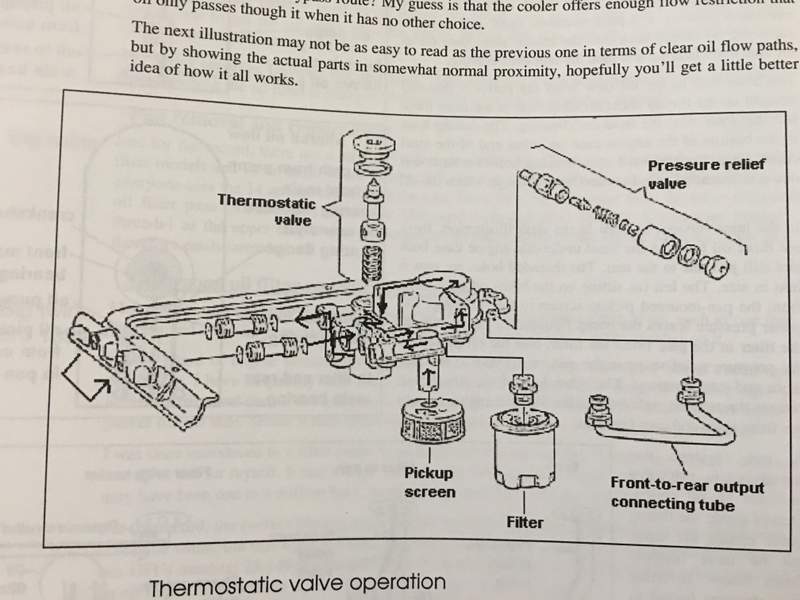
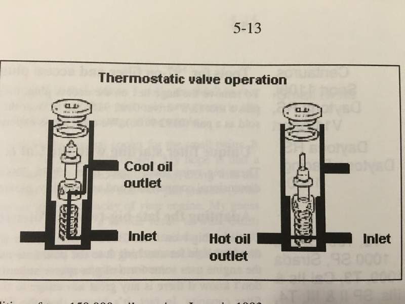
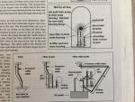
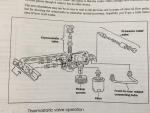
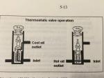
I have found a description in Guzziology that gives a description of the bottom end part of the system and have attached the accompanying pictures. I also located in an old post from 2006 from Pete Roper this description: So lets look at how oil gets to your bearings. Well, it starts off in the sump. In the case of the V11 'Broad Sump' motor the pick-up protrudes down to close to the bottom of the sump from above, through the gauze screen designed to take out the 'Big Lumps' should any suddenly appear! The pick-up goes more or less directly to the pump, this in itself is important because, and here is one of the most important things to remember when dealing with anything that is being pumped, THERE IS NO SUCH THING AS SUCK! The oil pump doesn't *SUCK* oil out of the sump, all it does is create a low pressure area within the pump body and the gas pressure within the crankcase will PUSH the oil up the pick-up and into the pump. Once the oil is through the pump it is then under pressure and being forced along mechanically but until it gets to the pump it is only being pushed by a fairly weedy sort of pressure. For this reason it is important to have as few impediments to flow as possible, that means a short, wide, gallery with as few bends as possible. While the pick-up on the V11's is quite nice and large the oil does have to turn through 90 degrees, twice, before it reaches the pump and the gallery in the block is no bigger than the earlier motors. Once the oil is through the pump and pressurised it is sent to the filter where the bits are strained out, (we hope!) the good news is that Guzzi motors are very clean and there isn't much inside them to wear or shed bits of 'emselves and load a filter up. Once filtered the oil then passes on to the oil pressure relief valve which is contained within the oil filter/thermostat housing bolted to the bottom of the block. The purpose of the relief valve is simply to prevent the oil pressure rising too high either when the oil is thick and cold and possibly at higher RPM. The oil itself has internal friction and if the pressure is too high it will both sap power and also try to spin the bearings. While the 'Ring' type main bearing inserts Guzzi uses are not prone to this and the back clearance of the shells to rods also seems to be pretty good a spun bearing is a rare thing in a Guzzi, or any other engine, nowadays but it can happen. Maintaining the correct oil pressure also means that the filter won't become over-pressurised, pop it's gasket or explode, which tends to be messy! After this the oil will pass over the thermostat which, when it gets hot enough, opens and allows the oil to pass through the cooler before going off for delivery to the bearings. From there on the oil simply has to get to the bearings and it does this through a series of galleries and pipework bolted on to the bottom of the block, essentially though it's very simple. After the thermostat the oil delivery is split. Some of it is sent to the front main bearing, some of it to the back. Both front and rear mains have a groove in the centre of the bearing face that allows some oil to circumnavigate these bearings and from there go on to the front and rear cam bearings. Also, above this groove, in the journal of the crank's front and rear main there is a hole drilled at a 45 degree angle in the crank itself that goes up to the crankpin. The crankpin itself is hollow and cross-drilled so that once the oil has filled the gallery in the pin it can flow out thrugh the big end bearings and out of the side clearance of the rods. The camshaft too has a gallery running down the centre of it and some, but not all, Guzzi cams have cross drillings to allow oil that is forced up the inside of the camshaft to spray out and feed various bits like cam followers with oil by splash, Some of the more aggressive aftermarket cams even have cross drillings in the cam lobes themelves. Finally oil travells up one further gallery to the top of the block above the front cam bearing where there are two drillings, one to take the oil pressure sender unit and the other one that takes the feed to the rocker gear in the cylinder heads.
-
Do I need hylomar? For the cleaned bottom 2 bearing flange holes and bolts should I use loctite blue or hylomar or the teflon thread sealant? I thought the loctite medium blue was also a thread sealant. What about on the breather tube gasket? I will use a new gasket, but do I need to coat both sides of it with the hylomar or some other sealant or just use the plain gasket. It is not leaking now, but I will be doing this based on the recommendation to replace the gasket and the fact that I need to remove the breather tube to JBweld the cam plug (which also is not leaking). Neither the bearing flange bolts or the breather tube are under pressure so maybe I am over thinking this. The cam plug is likely receiving oil pressure and could leak significantly if not sealing properly.
-
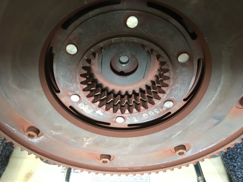
Are you referring to both the flywheel bolts and the clutch plate bolts? And you apply the weatherstrip to the bolt threads? What weatherstrip do you use. Why not use one of the varieties of locktite instead if you are using it as an adhesive? Do you put a small dab of grease on the end of the clutch rod that goes into the clutch assembly or is this left dry?
-
I had not planned on greasing the splines as I have never seen them greased and I think it would fling off. I'll look into the graphite. My flywheel bolts look like there was something on the threads but they came out without difficulty. On numerous other cars that I have done I have never locktited the bolts. I was just wondering what the consensus here was for the V11. fotoguzzi, thanks for the offer of the alignment tools. I very much appreciate that. I will email you. My clutch discs both measure 7.8mm and look undamaged. I read on another post here that that is the spec for new plates. The bike only has 5800mi. so I would expect that.
-
docc, I read you thread on 'sticking clutch' and checked my hub nut and tab washer and all looks good. I was not sure after reading the thread if you went with new parts or changed your mind and put it back together with jut a good cleaning and a new tab washer and just clutch discs. Did you use loctite on the flywheel and clutch retaining bolts or just torque to specs? I am making out my to buy list and so far I got pan gaskets, breather tube gasket and the long rubber breather hose. I am contemplating making my own breather hose as I am tired of buying these expensive crappy hoses for all my bikes. I have sourced 18mm ID oil rated hose and I would just need to get a couple of elbows and clamps. I just want a hose that wont dry rot. I also came across someone selling steel braided fuel hose in various diameters while searching for breather hose. I was wondering in anyone has an unusable damaged clutch hub they want to sell. That would sure make my clutch alignment go easier. I did manage years ago to do my T3 clutch without a tool with a lot of care lining everything up.
-
The manual shows the components individually but not an overall flow chart of the oil path that I could find.
-
 I was curious how the complete system works from the oil pickup to everyplace it goes to and in what order and how it returns. I was hoping that Guzzi had published a diagram of this. Thanks
 -
That engine may be missing but it sure is quiet. There was a hammer in my initial post picture too. I thought a hammer was mandatory for posting pictures.
-
Here are some pictures of the clutch hub and disk splines. I see some slight signs of wear. I am just going to clean it and put it back together.