Kiwi_Roy
-
Posts
2,378 -
Joined
-
Last visited
-
Days Won
62
Content Type
Profiles
Forums
Events
Gallery
Community Map
Everything posted by Kiwi_Roy
-
I have never tried it myself but one way of checking for an air leak is to pass an unlit propane torch around the intake. Any leak will suck in propane and make the engine speed up. Do this outdoors of course. How many miles(km) on your bike, I would expect the throttle bodies to last at least 80,000 kM before wear is an issue. Hopefully someone with a lot more experience than I will speak up.
-
Have you tried adjusting the idle stops with the little allen grub screws in the throttle bodies? They show clearly in this topic Frequently Asked Questions - TPS Setup and Throttle Balance Tuning You start with the screws backed right out Is it possible the fast idle cam is holding the throttle open?
-
The loose connector under the tank seems to be a common problem, mine did it for a while but it came right before I got motivated to fix it. Depending on the way the bike is wired, some bikes power the start relay through the ignition switch, that's a problem waiting to happen, the starter solenoid wants to draw about 50 Amps for a split second while it engages the gear, any resistance in the circuit and it has dificulty. To tell if it's wired through the switch pull the relay and measure for voltage at the socket pin 30 (the one off by itself) with the ignition switch Off. The best wiring IMHO is where the 30 contact is wired direct thru a fuse from the battery. Note: The starter draws 50 Amps through a 15 Amp fuse but not long enough to blow it. With age the grease in the switch goes hard and it tends to take pressure off the contacts so they don't make a good contact, your bike is at an age where the switch should be cleaned and the grease replaced with fresh petroleum jelly aka Vaseline. The same applies to the other handlebar switches, you will be surprised how much easier they operate with fresh vaseline. Don't use any solvents in the switches, some contact cleaners are dynamite on plastic parts.
-
I'm pleased to report we were able to sort out Steve's immaculate LeMans, what a beauty We found the TPS set very high, about 300 mV but it looked as though it had never been tampered with yellow paint in the fixing screws. Steve has fitted a mixture indicator which came back into line once the throttle bodies were all lined up as per Dlaing method on the FAQ She ticks over like a Swiss watch. The bike is in good hands with her new owner, obviously very fussy about having things just so.
-
I believe you open the air bypass screws to adjust the idle, both by the same amount. http://www.v11lemans.com/forums/index.php?showtopic=12204
-
You should have 5 Volts DC across the TPS. If you unplug it you can test the resistance as shown. Roy ECU Test Points.pdf
-
I took a look at doing that, it's a great idea, there must be a couple of useless liters over the hump. If you tilt the bike over to get it to the left side the pump will throw it straight back then start sucking air again. How will you install the line and hold it in place?
-
Perhaps it's just for a Push /Pull arrangement very common on Japanese bikes
-
Thanks gentlemen, that will certainly give me a good start. Roy
-
Something I have never tried to do is adjust the suspension, I just left it where the PO had it set. I have changed the oil in the front forks so its no longer valid. I'm sure I'm not the only one who finds this all a mystery. My 2001 V11 Sport has the rear susspension with white spring and blue adjustment nuts/knobs. I can figure out the large castelated nuts are for pre-load but how do you set that, is there a measurement to take while sitting on the bike? What does the knurled collar at the other end of the shock do? Then there's the valve on the little tank off to one side, it's all to much. At the front of course there's the compression rebound valves, what's the proceedure there? I immagine that once it's all set up and you take on a passenger or load up for camping you should adjust the pre-load. Thanks in advance Roy
-
That's a brilliant idea, I have often wished I could give it enough throttle so I could take my right hand off to do something, the stock cam doesn't quite do it.
-

V11 Le Mans fuel lines, which one goes where?
Kiwi_Roy replied to Dazguzzi's topic in Technical Topics
So it's like this then Fuel Circuit.pdf The bottom sketch that is. The top sketch is my V11 Sport -
V11 Le Mans fuel lines, which one goes where?
Kiwi_Roy replied to Dazguzzi's topic in Technical Topics
The fuel circuit should go tank - pump - filter - both injectors - pressure relief valve - back to tank On some models the pump and maybe the filter is inside the tank, on others it's bolted on under the tank. The pressure relief valve on mine is a small unit about 1-1/2" diameter fitted to the return connection of the tank on other bikes the relief valve somewhere in the hose between the injectors and tank. The relief valve setting is 34 - 40 PSI The pump circulates the fuel around as long as the engine is running No, you can't just run one hose to each injector they can be connected Y fashion or with a hose that passes by one then the other. Fuel Circuit.pdf -
Preliminary - I will refine this with some feedback, please offer your critique. I am hoping the relays on all our bikes are in the same sequence, if not please advise your model and relay order. Here goes If you are stuck beside the road with a dead bike and you suspect it may be a bad relay here's how to check them out Pull all 5 relays and with the bike in neutral try them one at a time in the start relay spot, Slot 1 on most V11s I think. (you may need to take the bike off the prop stand for the starter to crank) The start slot gives the relay a pretty good workout, an inrush current of 40 - 50 Amps and requires good contacts for the starter to crank. Once you have tested each relay take two that you know are working and put them in the ECU and Power slots (4 & 5 I think), Now when you turn the key on you should hear the fuel pump prime for a couple of seconds (you may need to take the bike off the prop stand) Put another good relay in the starter slot and the bike should crank, start and run however if you still have a good relay put it in the headlight spot (slot 2) Notes: 1/ If the bike has several 4 pin relays and one or two with 5 pins the only slot that needs 5 is the start relay the 4 pin variety will cause the starter to crank but the fifth pin is used to power up the headlight relay. Five pin relays can be used in every slot. 2/ The safety relay slot doesn't need a relay for the bike to run once off the propstand, this relay keeps the bike running on the stand in neutral 3/ Once the bike is running the start relay is no longer required for running but still used to power the headlight Once you are safely home in the garage you can get a bit more scientific Relay is it energized.pdf
-
Had to google channel locks. What we in Blighty call mole grips I guess or near nuff. As a committed tool fetishist, the three legged wotsit keeps me happy. Yea, Channel Lock is a brand name they also get called Water Pump Pliers, slip joint pliers and probably lot's of other profanities, Mole Grips I remember from down under.
-
I agree, hand tight with a hose clamp for security and they will also come off by hand, if a bit stiff you can pry them off with a screwdriver levered against the post.
-
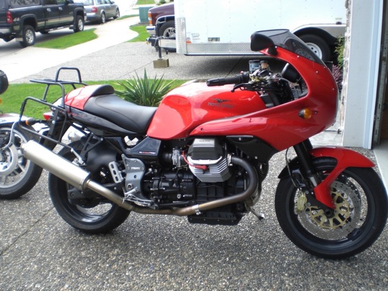
Buzzard We need you to post some more pictures of that bike, what we can see looks spectacular
-
I'm sure the Rosso is very similar to the V11 Sport. It sounds as though the ECU relay is not picking up as it should First relay 4 picks up, that triggers the ECU which picks up Relay 5 to prime the pump. If you pull both relays 4 and 5 With the key on you should see Voltage at Fuse 8 (if you have electric petcock) and Test point "f" Turn key off, insert relay 4. key on Now you should see Voltage at Test point"g" Turn key off, insert relay 5, key on you should now hear the pump for a couple of seconds. If none of the above The kill switch and start button plug into the loom - Guzzi Wiring - Simple.pdf Test Point Layout.pdf Your relay and fuse layout might be different but I suspect the're very similar Relay bases can develop a high resistance sometimes, loose contacts, corrosion. Relay Base Repair.pdf I will send you a PM
-
Thanks for the Vapour Lock link, my buddie and I are planning a trip to California in August, I'm sure it's much warmer than here in BC so I will put some insulation back. I/m guessing the fuel boils right at the pump suction since rubber is such a good insulator. Just out of curiosity I looked up gasolene boiling point. http://www.engineeringtoolbox.com/fuels-boiling-point-d_936.html It was explained to me that the wide range of boiling points is due to the different components, Im guessing that only one or two of the lower temp ones need to flash off to cause a bubble.
-
As others have said, if both front and rear lamps are on (assuming you haven't just replaced the lamps with LEDs it's likely the flasher can. I think LEDs use a different electronic flasher with 3 terminals, the 3rd one grounded to the chassis.
-
You have me curious, I replaced all the hose on mine last year and left off a great wad of insulation the PO had applied. Please point us to the vapour lock thread
-
Sorry Hubert, As I said there's so much information out there. I'm not saying the author doesn't know what he's talking about I just don't think it applies in our case. Our bikes with Ducati Energia regulators are more like constant Voltage chargers cutting off at 13.8V with the headlight relay 14.4 without, not constant current as per the article. His curves are interesting though, note how the flat part of the curve gets closer to the setpoint as the C/time drops. I suspect we start out at C/1 and work our way up towards C/20 covering a very wide SOC band. Battery Curve.pdf I also suspect these curves are just freehand sketches (which is quite ok) not something that was actually plotted. You may wonder why my 2 setpoints are different by 0.6 Volts, it just so happens that's the voltage drop I measured on my bike from battery + to the black wire others will be a little different, some more, some less.
-
I got a screw in my near new rear and have a plug. I find it hard to belive someone would toss out a new tire in spite of what they say.
-
There is so much miss-information about batteries on the web it's hard to get it straight anymore. You ask about the difference between 13.9 and 14.5. If you look at any reasonable Voltage vs % charge curve 0.6 Volts amounts to about 30% of charge. The idea of adding a "Trick" diode is just to restore the status quo after adding headlight relays that's all. Luigi was tricking the regulator by dropping voltage between battery and reference wire, adding relays foiled his trick Have you checked the diodes in your regulator, not being able to recover sounds a bit like mine when one of the diodes let go. I think the charging on the V11 is quite good when it's working as it was intended, the alternator certainly has enough capacity.
-
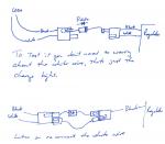
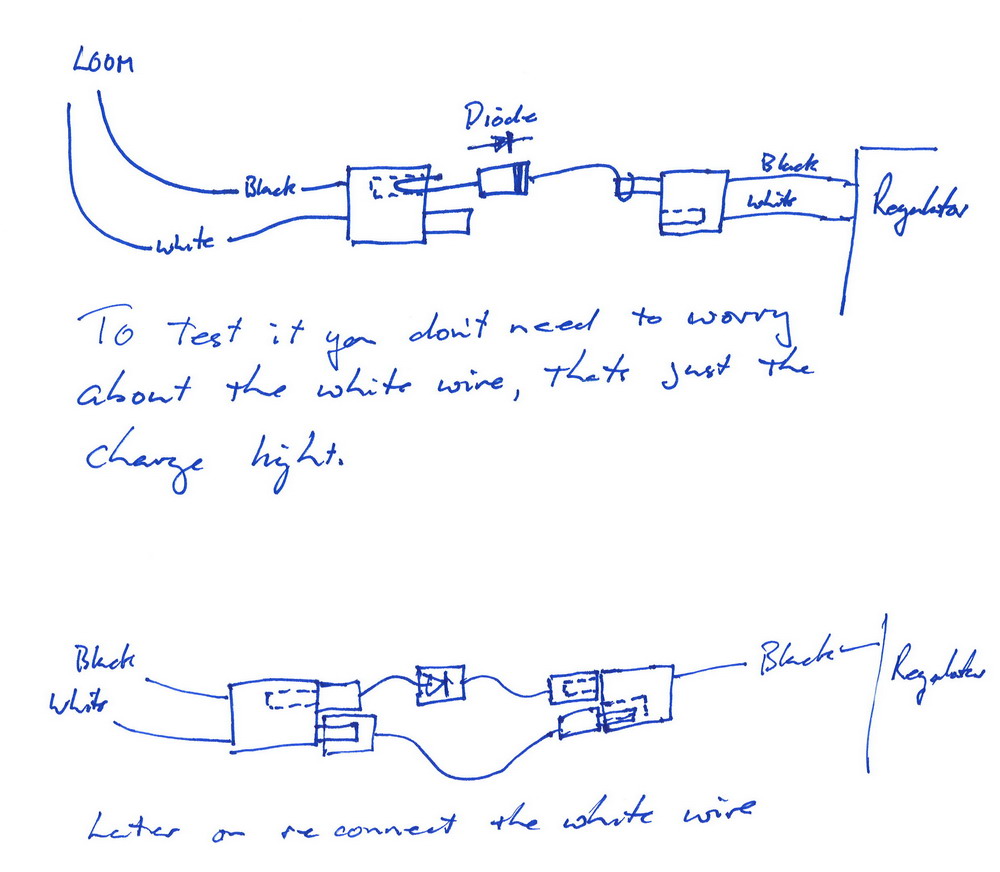
You can boost it up by 0.6 Volts simply by adding a diode in series with the black wire. To test it unplug the Black/White plug and turn it half a turn so only the white one is connected then take a diode wired to a M/F bullet connector and connect the other two. Something like this. White-------> >-------White---|regulator| Black--- - Diode Sorry, it doesn't display how I want it, I will do a sketch