Kiwi_Roy
-
Posts
2,378 -
Joined
-
Last visited
-
Days Won
62
Content Type
Profiles
Forums
Events
Gallery
Community Map
Everything posted by Kiwi_Roy
-
Hi, The speedo cable on my 02 V11 Sport is broken. I have ordered another one but the dealer expects it to be a month or more. Can someone tell me the speed in kmh for 1000 RPM in each gear so I can ride by tacho in the meantime. Thanks in advance Roy
-
Raz, I take it you used a resistor instead, about 120 Ohm I figure. You would need to use at least a 1/2 Watt to keep it from overheating. The incandescent lamps has one slight advantage over the resistor in that it's resistance is low when cold (~10 Ohms), this should provide more current to the thermistor so it heats faster and it goes up to about 150 Ohms when on. Having said that I might have used the resistor but I didn't have one to hand. How did you get on with the lampholders? I haven't tested mine with an empty tank yet. I doubt the bulb will ever burn out as it only turns on slowly but if it does it will be fail-safe as you say. Cheers Roy
-
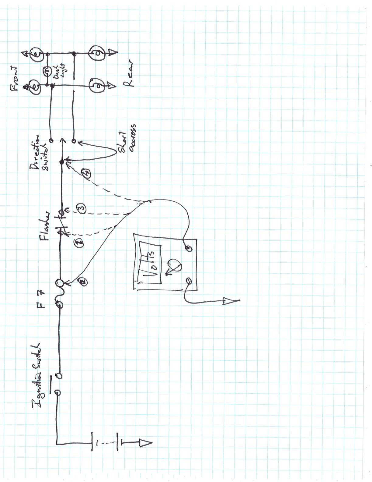
I installed LEDs to replace the Incandescent lamps in my V11 Sport. I had a few problems which I will list below in the hopes that others will benefit. I ordered 74-R lamps from SuperBrightLEDs , 1 Blue, 2 Green, 3 Red $1.19ea. http://www.superbrightleds.com/cgi-bin/sto...mini-wedge.html 1) First of all I tried a direct replacement without success. The bases look similar but on close examination the LED contact wire is wrapped around the end of the base and bent back so it makes contact on both sides (see print) shorting out the lampholder. I tried clipping one side off the wire, this works but not well as it's a little tricky getting it into the base. Since the LEDs are long lasting I decided to remove the contacts and solder the lamps in place. The rubber base comes out quite easy with a bit of tugging and the new lamps fit snugly. 2) Because the wires have oxidized over the years I had dificulty getting a good solder joint so I clipped the brass contact off leaving the crimp part which is much easier to solder too. Once the wires were connected the lamp slipped back into the rubber base. 3) Unlike incandescent lamps LEDs are uni directional (diode) so you need to make sure they are connected up with the right polarity by turning on the ignition and touching the lamp to the wires. Current in the flasher circuit indicator lamp flows in both directions from the active side to the non active side so it needs some additional components. I added a bridge rectifier from Radio Shack. A couple of diodes will also work if the negative side of the lamp is connected to the chassis (see print). 4) My V11 Sport has a thermistor type low fuel sensor, this draws about 20 mA with the tank full. The heat this produces is carried away by the fuel. When the fuel is low the thermistor is no longer kept cool so it heats up, the resistance drops, the current goes up some more until it draws enough current to light the incandescent lamp. Unfortunately the 20 mA the lamp thermistor draws turns on the LED as it only requires 10 mA for full brightness. The solution is to add some additional load in parallel with the LED. I could have used fixed resistors but one of the old lamps in parallel does a better job. If your bike has one of the reed type level switches the additional load will not be required. In hind sight I should have ordered 6 new lampholders from SuperBright to replace the Guzzi ones. These would have saved me some work and they wouldn't short out like the Guzzi originals. I don't see a suitable holder on their website but I'm sure they have one. (the T10S-SP is too large) The colour of new LEDs should match the colour of the lenz otherwise they will look dull. If you have trouble pulling the old glass lamps, pull the rubber base out or a slide piece of plastic tubing over the lamp so that long nose pliers will get a better grip. Although it took me about 3 hours I am very pleased with the results. The LEDs are more visible in bright sunlight. While I was at it I added an LEDs to the N/O contact of each relay, but that's another story. Have Fun Roy Guzzi_Lamps.pdf
-

it's spitting back alot and wont run well
Kiwi_Roy replied to motoguzzimick's topic in Technical Topics
Take a look at my post "Throttle Position Offset", you might find it usefull Roy -
Hi, A set of Tekno saddlebags came with my V11 Sport, These have faded in the sun to sort of light purple colour. Does anyone know how to restore these to Black. I cant seem to find who makes these, does anyone know manufacturer, web site etc. Thanks in advance Roy
-
A quick check you can do with a multimeter (or 12V lamp) With the key on, unplug the flasher, is there 12 V on one terminal If No check Fuse F7 If Yes and none of your 4 flashers light up no matter where the switch is the chances are its in the switch. Its quite easy to pull the switch apart but be carefull not to loose any of the small parts. Once you have it apart turn on the key and short between the center terminal and either of the outside terminals with the key on if the flashers go the fault is in the switch. You can also check for voltage on the center terminal. I doubt it.s in the wiring from switch to flasher lamps, it would be quite unusual for both sides to go at the same time. Keep us posted. Roy
-
Thats great news. To prevent future problems apply petroleum jelly (vaseline) to the terminals. This keeps the Oxygen from the metal so that Lead Oxide cannot form. Lead Oxide is a hard light grey insulating layer that mostly forms on the negative terminal. I learned this trick as an apprentice working on large traction batteries. Roy
-
Yes, you could easily measure it but that makes it more complex. The idea was to set the pot for best performance then square it all away later e.g. measure the mV with the throttle closed, remove the circuit and set the sensor to give the same mV I haven't tried it and probably won't get a chance for a while (next riding season) Regards Roy
-
Thanks Rachethack, I will remember your advice. I don't worry about that sort "What upsets me would kill most people" I woke up in the middle of the night and thought perhaps +/- 750 mV would be a bit extreme so I revised the circuit to show a series resistor to drop the voltage down to about 0.5 Regards RoyGuzzi_Trim_Pot_2.pdf "I have to figure out this file attachment thing eh" Guzzi_Trim_Pot_2.pdf
-
Hi, I am very new on this forum but I spent my working life troubleshooting electrical and electronic equipment. Seeing all the posts re Throttle Position Sensor I was wondering if anyone has tried adjusting the mV on the fly. The simple circuit attached would cost pennies and allow you to raise or lower the mV while riding to find the sweet spot. Once found you could then tweak the position sensor and remove the temporary circuit. I would just solder the two components directly to an AA cell and tape it to the bars. The battery would last several days with the components shown. What do you guys think? Revised sketch Guzzi_Trim_Pot_2.pdf Note re revision In hind-site the original sketch would have too many mV so I have added a 1K resistor in series with the battery, this will reduce the mV from +/- 750 to +/- 250 You could add a switch which will eliminate the offset when open and perhaps add a scale in mV to check the operation just connect your multimeter to the wire in and the wire out. None of the component values are critical. It is only intended as a temporary addition.
-
I assume you mean the fuse went when you pressed the start button, The only thing after the button is the clutch switch then the start relay. What is the number of the fuse that blows (fuse position from front of bike) Have you had any of the electrics apart recently? Roy
-
I found thet the 5 pin relay is a direct replacement for the 4 pin. My relay bases are the variety with slip in spade connectors. It's possible to slip these out by releasing the clip with a small nail so they can be replaced or squeezed with a pair of pliers to tighten them up. I will smear a little vaseline on the prongs before I put them in, this makes them easier to pull out and helps prevent corrosion. Roy
-
I just recieved a set of 5 relays from Digi-Key, $4.60 each. The postage to Canada $11.75 total US$34.70 I suggest you try to combine with a friend to cut down on postage My V11 has 2 SPDT and 3 SPST but I elected to go with all SPDT The 5 pin relay will replace the 4 pin relay without any wiring changes. The relays appear to be the sealed variety G8HN-1C2T-R RATED 20A for normally open, 10A for normally closed www.digikey.com http://search.digikey.com/scripts/DkSearch...p;x=17&y=14 Roy
-
Has anyone tried varying the throttle position mV while riding? It seems to me an easy thing to make up a pot to allow offsetting the mV +/- say 20 mV This would allow you to stop and move the sensor by an equivalent amount. Just a thought Roy
-
That is brilliant Arek, if you'll pardon the pun, did the indicator for the flashers work ok as well. I think the lamp color should match the colored mask that sits in front. I guess I will have to find another winter project BTW, have you tried out the low fuel light, in my V11 Sport I think it's a thermistor that requires a certain load. The lamp may need a resistor in parallel to supply this. Did you replace the Spedometer & Tachometer lamps also? Regards Roy Update - I ordered a bunch of lamps from Ultra Bright will update you once installed
-
I will take this on as a challenge, this sort of thing is what I do for a crust. I have been messing around with the idiot lights on my V11 and had the same thoughts as David. The bi-directional current for the direction indicators is not a problem, a bridge rectifier will fix that. As I see it there are two options, A) Insert LEDs into the existing sockets and wire the required matching resistors to the lamp-holders. Remove the existing lamp-holder base and make a printed circuit board with all the LEDs and resistors etc. on it. The advantage of A) is it would be adaptable to other light cluster patens. I will start experimenting with the different styles of LED available Regards Roy
-
You could try overhauling your starter e.g. new brushes and bushes. If the bushes get too worn there is a possibility that the armature is rubbing somewhere. Starters are quite simple or just take it into an auto electrician. I think the voltages you see are pretty reasonable. Roy
-
My 1996 MOTO GUZZI Sport 1100 LeMans story (long)
Kiwi_Roy replied to 96SportCarb's topic in 24/7 V11
Cuan, That's a great story. Like you I just fell in love with a VII Sport. I doubt I will be able to turn it into a beutifull creation like yours But I will love it just the same. Regards Roy