

Kiwi_Roy
-
Posts
2,378 -
Joined
-
Last visited
-
Days Won
62
Content Type
Profiles
Forums
Events
Gallery
Community Map
Everything posted by Kiwi_Roy
-
Yes, I am a journeyman Instrument Mechanic. Manometers are used to accurately measure low pressures. A normal Bourdon tube vacuum gauge has a range equivalent to a manometer 32 feet tall so your setup is far more accurate for a fraction of the cost. I will leave my modified grease nipples in place and cap them off. Regards Roy
-
I have the parts manual, I will take a look, thanks, Roy
-
When I put mine back I just set it with the same number of threads on both sides, Even then there's no threads projecting from the nut. Can it really be that important to line front and back to the nearest mm? I don't like the sound of those 8 ft flouro tubes, sounds like bit dangerous. A 2 x 4 would be safer, flip it over and average the reading. Roy
-
Thanks guys it looks like the washer is supposed to be there then. The previous owner was very picky about such things. I will take your advice and service the bearing. Regards Roy Update I looked at the part manual today, sure enough it shows the washer. I think I will stick it in place with a couple of spots of silicone so it doesn't drop down between the fork and inner bearing next time the wheel comes out. Roy
-
I pulled the rear wheel on my V11 Sport to get new tires fitted. If I look at the axle it has shiny spots as though the bearings have been spinning on it/ The bearings feel fine but I am wondering if a spacer or something is missing From the right hand side I have Large flat washer about 20 thou thick with a large hole (about 1") Transmission Spacer about 5/8 thick (item D in manual) Wheel Brake caliper The picture in manual doesn't show the large washer, I'm wondering if it's supposed to be there The hole in it looks as though it will fit outside the transmissions inner sleeve. Can someone confirm if it's required. Thanks in advance Roy
-
Guzz - I added my experience to another thread on removing the swing arm. Yes, I think I could lube it in-situ next time now I have filed the gun's nozzle to fit. It turns out that someone had butchered the two pinch bolts on the front universal so I'm glad I pulled it out. Cheers Roy
-
Your gauge looks like the Delux model LOL, it even has a scale! Slide a short length of rod inside or tubing outside and make a right angle bend at the corner, that will take care of the kink. My bike just had socket head screws but no tube between the bodies as mentioned in the write ups. Your manometer is much more accurate than using two gauges, I worked for many years as an instrument technician, That's what we used to measure low pressures accurately and where the unit "Inches of water" & "Inches of Mercury" come from. "Inches of ATF" in your case. A normal vacuum gauge has a range equivalent to a 32 foot tall manometer full of water with an accuracy of +/-1/2% (+/- 1.9 inches Water Column) so the differential reading could be out by as much as 2 x 1.9. The only thing that will mess your gauge is air bubbles in one side or two different fluids. Nice clean bench, mine is 3 layers deep in junk. Regards Roy
-
I just did my driveshaft today. Remove the two large bolts and the swing arm moves out of the way quite easily, there's no spring load on it and no need to disconnect the shock. When you replace the driveshaft be very careful lining up the pinch bolt holes with the reduced portion on the spline. If it doesn't line up properly the threads will catch on the splines. A couple of the bolts on my bike have been stripped that way. (you have to remove the bolts before you can pull off the universal joint) When replacing the swing arm pivots it's quite difficult to get the thread started without crossing it. I found if you run the nut up next to the pork chop it's quite easy to see if its straight. Put both pivot bolts loosely in place first, this lines up the swingarm. I ran the pivots up to where they just pinched the bearings, you can slide the swing arm from side to side before it pinches. In hindsight it should be possible to grease the front universal without removing the shaft, I tried this using a flexible hose up over the swing arm but couldn't get the end to snap on the the nipple. When I finally got the shaft out I had to file a couple of flats on the nozzle to get it to fit between the 2 halves of the universal. (even with it out I had to do that) Don't forget to line up the two marks if you pull the shaft apart. Good luck Roy
-
Guzz, The gauge was a no brainer for me, I am an Instrumentation Designer. It needs to have a few inches of rubber tubing at the ends where it connects to the throttle body so it doesn't drop off when hot.I will make another that can be used to check balance while the bike is in motion. Thanks for the grease info, so it's referring to overheating, I didn't understand that. I thought there might be some exotic seals or something. The PO was paranoid about lube materials, he gave me a crate of the special Italian oil mentioned in the owners manual. Cheers Roy
-
I used my new tool this evening, It worked like a charm. I did the TPS RH fully shut I found 102 mV so adjusted it to 150 This gave me a range 150 - 4890 mV. When I re-connected the linkage I got anywhere from 387 - 440 mV as I wrapped the throttle. This equates to about 1% of span so I wasn't too worried. I see several posts saying the mV should be about 500 with the linkage on. I adjusted the RH stop to give me ~500 mV. The LH body still on the stop When I attached the balance tool the difference was less than 2" of oil which is a very small error indeed. The bike was running about 900 RPM so I opened the left and right bypass screws until I got 1100 with both pressures balanced (about 1 turn on each) Then I ran the engine at about 3000 RPM, the pressure difference was about 4" so I tweaked the throttle linkage knob ever so slightly ( A few observations I figure that both throttle bodies should be sitting on the stop screws at idle because that's the most repeatable position 500 mV +/-10 mV. The 500 mV number is not really fixed like fully closed or WOT because it is effected by bypass screws and linkage backlash The main thing is to get a steady idle, I figure a repeatable mV should help there. Oil was a good choice of fluid for the manometer, during the test one of the tubes fell off due to the plastic softening with the heat, this resulted in some of the oil getting sucked into the other cylinder. I will find a short length of rubber tubing to modify the setup. Grease nipples are the cat's pajamas for connecting the tubes, just take the spring and ball out. I am confident that I have my throttle bodies well aligned no load. Next I will figure out how I can check it while riding with the motor under load. Once I have it to my satisfaction I will try out my Throttle Position mV offset rig. I cut the TPS wire near the ECU and inserted a M/F spade connector from here I will run a pair of wires to a mV source at the handlebars, I think +/- 100 mV (+/- 2% of span) should be about the right range Will keep you posted Roy
-
A similar thing happened to a buddy of mine on his KTM, accelerating around a curved on ramp and the back locked up. Of course he bit the pavement. to add insult to injury a cop came along and gave him a ticket for careless riding. Glad you're OK. please keep us updated, I have the same ride. Regards Roy
-
The manual says (picture of greasing the driveshaft) "To lubricate the cardan transissions use only saphonifying greasers with lithium of a grade 2 consistency, 265/295 penetration and with a dropping point of about 180* The lubricants must not contain additives with MOS2-33" Would someone like to explain that to me? My grease container says Heavy Duty Lithium and a few words of warning about not eating the stuff. It looks like pretty normal yellow grease to me but the manuals warning has me worried. Thanks in advance Roy
-
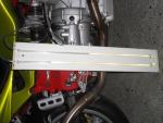
I finally got around to making a gauge for balancing the throttle bodies. 10 ft of clear plastic tubing and a lump of scrap metal. I used 10/30 oil as the fluid thinking it would be safer than water if it accidently got sucked into the engine. at first i thought it might be too viscous but when I tested it out seemed just right. Without making any adjustment I get about 8" at idle, falls away with some revs. I looked everywhere for barb fittings to screw into the body. Finally in a rare flash of brilliance i figured out 6mm grease nipples looked just right. I ground the back a little to let the spring and ball out, they work perfect. If I can just find some caps for them they will become a permanent fixture. Sorry about the sideways picture, just flip your monitor over LOL Cheers Roy
-
Yes, taking something of his bike for a reminder would be quite appropriate, How about those nice round nuts on the exhaust clamps, you could put them on your bike somewhere as a nice reminder of your friend, Every time you polished it. Cheers Roy
-
I downloaded the manuals V11 & Supplement. They all seem to come in 3 languages, rather than print all pages and throw away the ones I didn't need I took the file to work and opened the pdf with an edit program we have. I was able to get rid of nearly half the pages and print it out double sided. If anyone would like a copy of the abbreviated pdf send me an e-mail roy_matson at yahoo dot ca Regards Roy
-
That's really sad Peter, I'm sorry you lost your friend that way. I don't think I would even try and salvage parts off a bike like that, it should have been buried along with your friend. My V11 was in a similar accident, car turning in front but fortunately the owner came off with a few scrapes and i was able to purchase the bike and restore it. Broken headlight mainly. Again, my condolences on your loss Roy
-
That's great guys. I will have at it then. Will check out the manuals on the site you provided. Roy
-
That's great, I see you have changed the bars on your bike. This is something I need to do. Can you give me some details. Thanks Roy
-
I read the tech note about doing the valves. I have been putting this task off because I don't have new gaskets. Is it OK to put the old ones back? BTW, where do I get a decent manual for V11 Sport? Thanks Roy
-
Slightly off topic - when I replaced my relays I added an LED to the base of each one, It tells me if the relay is energized.
-
Thanks Tom, my bags are soft I will check out the spray next weekend. Will keep you posted. Regards Roy
-
Great idea, as an electrician I looked at the schematic and worried that the headight might fail with all those contacts in series. Using a separate relay for each filament should mean at least one will remain working. As a winter project I added an LED to the base of each relay wired to the N/O contact that way I can tell at a glance if one has failed to pick up Roy
-
Tried filing Aluminium, it soon clogs up the file. One of these surform files work great for removing a lot of metal in a short time. http://www0.epinions.com/Stanley_Surform_File_Shop_Tools Roy
-
I couldn't find a speedo shop locally, The shroud had a bad kink, must have got caught in the steering somehow. and very rusty otherwise I would have just replaced the inner with a kit from the local auto parts store. I put it on my Christmas wish list but unfortunately the one the supplied wouldn't fit. Apparently they have to get one from Italy. I'm not too impressed by the local dealer but buying on line usually works out more expensive with duty and broker fees. Thanks for the lube tips Roy
-
Thanks guys, that's just what I need

