

Kiwi_Roy
-
Posts
2,343 -
Joined
-
Last visited
-
Days Won
61
Content Type
Profiles
Forums
Events
Gallery
Community Map
Posts posted by Kiwi_Roy
-
-
When your bike is cold ( before first start of the day ), check the resistance of your oil and air temperature sensors. They should be the same and correspond roughly to this table - http://www.cajinnovations.com/MyECU/temperature.htm
Also check your bike's rolling resistance - are any of the disks warm?
I checked the thermistors last night, both about 4.75 kOhm
No the brakes are not getting warm
Atached is the calc Raz asked me for, basicly the higher the temperature the sooner choke flow occurs, this is because the vapour pressure is lower. The change in density is insignificant.
The change in flow about -9% for 50°F temperature rise.
I don't claim that this is accurate, gasoline is far too complex for me to calculate, it just shows what happens.
Roy
-
Could you try that with the program please? I wonder if this can explain some theories my dyno guy had regarding fuel temperature.
Yes cavitation is a problem, it destroys pumps and control valves. You may hear it hapening when you open a water valve in your house, sounds a bit like gravel going through the valve, flashing is not so bad.
Calc sheet sent to your e-mail.
Note gasoline is a very complex liquid so it's hard to model exactly but this gives some idea.
Regards
Roy
-
#1 fuel pressure does make a difference on gasoline fuel injection. You clamp off the fuel return and see what happens.
Yes you are correct the fuel supply pressure does make a difference but the downstream pressure doesn't because it's always under choked flow conditions.
In other words if you hold the supply pressure constant, while the injector is energised the instantaneous flow rate is exactly the same at idle (greatest vacuum, greatest DP) as it is at WOT (no vacuum).
So the pressure drop changes from ~50 to 37 with no change in the instantaneios flow rate.
It's quite neat really, to increase the fuel flow you just hold the injector open longer.
If you refer to the calculation sheet I posted you will see this, the first 3 calculations warn of choked flow
-
Yes, I was certainly very happy until I got the panel back together and the dang light was not working again! Must be something loose or not making a good connection?
The sockets on my V11 are the worst, no better than you get on a string of Christmas lights. I pluged in an LED replacement and they shorted right out. I ended up soldering the new lamps in place. LEDs should last me out.
Roy
-
Hold it for a moment. Is this really what is happening at the injector nozzles in my bike? The model Roy used does not apply I think. Not in this context.
Make the same thing again and vary Inlet Pressure and Atmospheric Pressure. The pressure loss then should be a result of the resulting flow (velocity, length of nozzle, design of flow channel and valve needle etc). Not vice versa.
Hubert
Hubert,
Yes if you change the inlet pressure (as it would with the spring housing connected to inlet manifold) in the sizing program the flow will change but if you only change the outlet pressure (manifold pressure) once the pressure drop exceeds 20 psi the flow stays exactly the same.
Basicly what happens with choked flow in a liquid passing through an orifice, the pressure drops (vena contracta effect)past it's vapour pressure and vapourises which takes up more space than the liquid thus choking the flow off.
I found several quite good explanations on the web.
I like Dan Ms explanation of why Guzzi chose this approach.
My guess is they decided to simplify things and go for a known flow variable time. Obviously at one time in the past they tried changing the pressure based on manifold vacuum as it shows on the earlier document with Webber fuel injection. See earlier post
The pressure loss is fixed in this case by the regulator and throttle position. I'm not saying the injector is as simple as I make out but I expect the valve portion is much larger than it needs to be relative to the nozzle orifice.
Perhaps someone can find something on injector theory.
BTW, are the injectors something that needs to be replaced occasionally?
-
OK, now I'm convinced.
I was having a hard time understanding why connecting to the manifold would have no effect.
I work in process control design so I used a valve sizing program we use to model a hypothetical injector to see what effect changing the pressure would have.
As I see it an injector is nothing more than a simple On/Off valve followed by a fixed orifice.
As you can see from attached once you go past 20 psid the program gives a "Choked" flow warning
Choked flow is a condition where no matter how low you drop the discharge pressure the flow will not change.
At a fuel pressure of 37 psig the injector is well within choked flow condition for any senario.
The only way to change the flow rate is to use a larger orifice or hold the injector open longer.
I'm really sorry I wasted your time with this
Regards
Roy
-
Roy,
You've looked at your CO trim with a software interface?
No, I haven't done that yet, I'm sure its a long way off.
Something else that makes me think so I park in an underground garage about 20 ft away from the CO sensor that starts the ventilation fan. If I start the bike it quickly triggers the fan wheras nearby cars in the same garage can start-up and leave often without triggering it.
Re regulator connections see my next post.
Thanks
Roy
-
Have you re-set the TPS starting all the way from base line?
Yes I started with the 150 mV with the stops backed off and choke clear.
My idle reading is ~ 460 mV
A little history
I purchased the bike late last year. It came with a power commander.
Earlier this year it started to miss badly so I disconnected the power commander and put it back to standard, It runs well but seemed to be using too much gas. 8L/100 km at highway speed
I thought to myself OK, I will start from scratch, get it running as well as possible then put the power commander back
After reading all about the TPS (all 100 pages) I re-set this at the same time adding a little black box that allows me to offset the TPS while riding.
I found that even changing the mV by about 250 mV has little effect on performance.
I figured that the bike is so rich that even reducing mV by 250 still doesn't approach lean running.
My question
Does the power commander add/ subtract from the map inside the original ECU or does it completely replace it,
In other words even though I am way too rich with the standard map will putting the PC back start me off from scratch?
Thanks
Roy
-
Sorry Roy, we've been over this before and I believe it's no use. I was as enthusiastic as you until I was convinced (from empirical tests made by Dan M, can't find the original thread now but a resume is at http://www.v11lemans...dpost&p=159156) that connecting that hose it will only work as a switch. It will not change the pressure linearly with the intake manifold. I also believe it will break prematurely.
OK, I will take your word for it, that document must be an old one, I think you mentioned that.
Please see my next to fotoguzzi.
Thanks
Roy
-
Oh, also...the R4 & R5 relays...ECU and Injection is it?
Anyway they're smaller than the other 3.
Do they have different values or can I order all 5 of the better relays?
Here are the relays Order all 5 pin, they are interchangeable
http://search.digikey.com/scripts/DkSearch/dksus.dll?Detail&name=Z2247-ND
Digikey also have the little switches that go on the Brake / clutch levers
Regards
Roy
-
I hate to disagree with you guys who have multi year experience
This is the document that prompted my question
http://www.dpguzzi.com/efiman.pdf
On page 7 it talks about the regulator connected to the manifold and why referring to the diagram on top of page 8
Also the picture on page 3 clearly shows the regulator connected to the manifold.
Could it be that it is talking about an earlier model?
I have been searching for a reason why my V11 Sport is running so rich ~ 8L/100 km so I clutched at this straw.
BTW I work with and specify regulators all the time. (Process Control Instrumentation)
Actually once i took the time to read the whole document it's refering to a Webber ECU of earlier vintage.

Roy
-
I have never seen a Guzzi w/that connection. they always vent to air.. the regulator just has a big spring in it, I don't think manifold pressure would have any effect.
Yes it would have a huge effect, connecting the spring housing to the manifold would drop the pressure by whatever vacuum the manifold is running. At idle it would be 33-14 psig, at WOT it would be 33 psig. That kind of makes sense in a way the flow thru the nozzle constant and metered by length of Open pulse, I'm trying to find the link
With the spring case disconnected the gauge pressure is constant (pressure measured with a pressure gauge)
With the spring case connected the pressure drop is constant (pressure measured with a differential pressure gauge)
Raz, would you please attach that link to this thread, I completely lost it.
BTW the diagram is a bit confusing because it shows two regulated pressure connections, The bottom one goes back to tank and the top barb connection is the one the text is refering to.
Roy
-
Hey, Roy, check those pdf links on post #1.
But Guzzi Wiring Layout April 24 2010.pdf brings up a prior test point layout, and not the "Simplified Wiring Diagram."

OK Docc, all fixed "I hope"
The latest files are right at the top of page 1
Thanks for picking that up
-
In a document Raz refered to regarding ECU on the bottom of page 7 talking about the fuel pressure relief valve it mentions connecting the spring case to manifold thus keeping the pressure drop fuel to manifold pressure constant.
I seem to recall recently the subject came up on another thread and we were told it shouldn't be connected.
Which is correct?
I ask because the regulator on my bike is not connected to the manifold and it runs very rich which of course it would with 30% too much fuel pressure ( flow and pressure drop are a square root relationship i.e. to double the flow you need 4 x the pressure)
It seems to make sense that you would want the pressure drop constant and not the pressure to atmosphere.
Thanks
Roy
-
Roy,
Will you be posting a 'final' revision?
Docc
The latest rev is attached to my first post in the thread
Guzzi Wiring & Guzzi Wiring layout April 24 2010
No, if you see anything wrong or some way to improve please let me know.
I still need to do one of the lighting and a detail of thr ECU wiring
I would also like to add the wire colours but as text not screen colour.
-
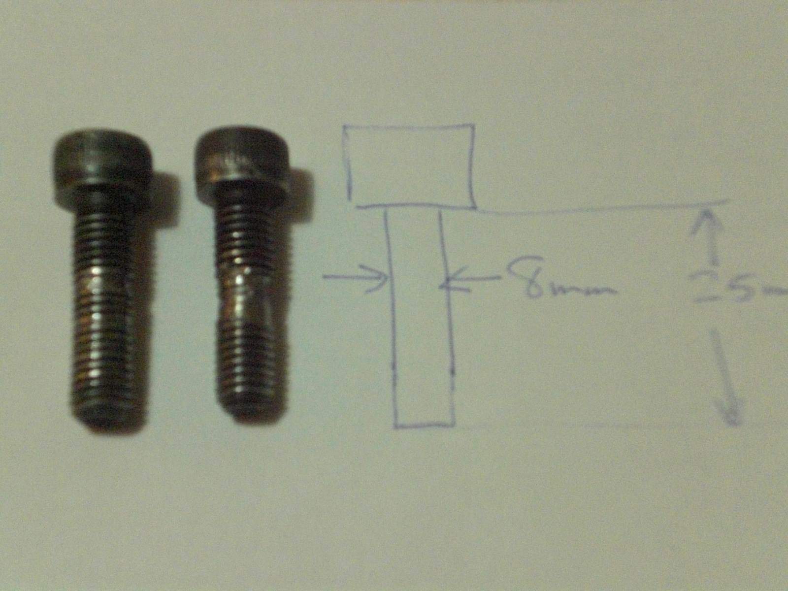
screw threads are toast - looks like they used permanent loctite on them. I ran a tap throught the u-joint ends - threads look great - but I want to make sure I don't err on the replacement screws.
Thanks!
Mike
Picture attached -
The threads on mine were the same.
The bolts are marked LOBO 12.8 with 2 dots
This is caused by not lining the indent in the shaft up perfectly with the bolt hole.
The bolts catch and destroy the thread.
If you look through the gap between two halves you should be able to line it up.
Sorry, I don't know the torque settings but I doubt it's critical. I just tightened mine
by hand to where It seemed right.
By the way the original bolts were longer than necessary, 25mm is long enough
"Tighten them till they strip, then loosen 1/2 turn", just kidding
Roy
-
aha, story goes on.
not charging, melting 30A fuse. Blowing 15 fuse on lights. So i am taking spare wiring loom from Ebay and let's see where is the gremlin now

Strip the ignition switch down while you are at it, the voltage shouldn't be able to by-pass that as you describe
With the switch off and the bike not running pull each fuse one at a time and check for current using a 12 V lamp in place of the fuse.
I suspect you will find some wires melted / shorted together between the seat and the switch.
I think I would be taking a close look at the connector under the tank at front. Seems a bit like tracking across from one of the Positive wires to a Negative.
You really need to find out what's going on the potential arcing could cause a fire. With everything turned off I would remove all the positive wires and measure mA from positive of battery to each of the positive leads, they should all read zero mA. If you see any current at all then you can try to track it down by pulling fuses etc.
If you can't find the problem, leave the positive wires off when you are not riding.
Report back
Roy
-
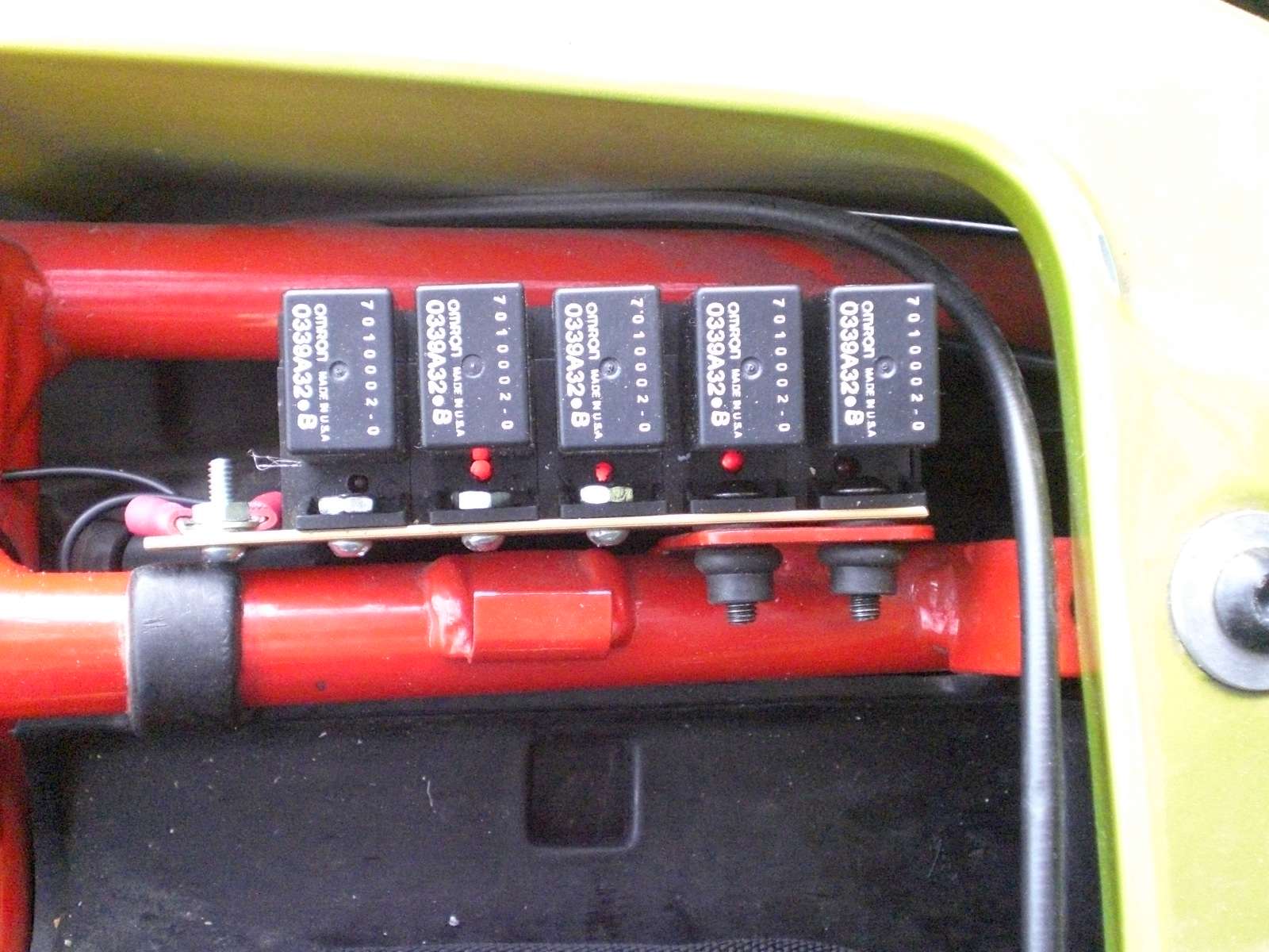
And heres a Photo. I added a strip of aluminum to tie the bases together so they don't flop around.
The nut and bolt at the left is for the common ground point for the LEDs
I strongly suggest you make a metal template for drilling the 1/8 hole so they all end up in the same place, not like mine.
Regards
Roy

-
Yes, I see that hot feed from fuse 5 now. No use using two LEDs there.And, I don't think I've ever heard of Relay1 failing in the open position.
Looking at an LED for Relay 3: This LED will light when the relay is closed by the neutral switch, but will also light when the sidestand is up and its switch is closed. The LED would only go out with both the stand down and the gearbox in gear. It would make for an easy check on both the sidestand switch and the neutral switch/relay3 circuits. But you would have to look at the LED first in neutral with the sidestand down (neutral switch/relay3 circuit) and in gear with the stand up (sidestand switch/no relay).
Thanks for having a look at that relationship. I first saw this with your Note 13 on the Test Point Layout. Am I seeing that right?
Good point, that light will allow you to test either.
A second LED across the coil might be good here or perhaps one of the 2 colour variety Red for Prop Stand, Green for Neutral relay, White for both.
BTW Suzuki use an almost identical circuit for their prop-stand / neutral switch. I wonder what % of bikes have the side-stand switch jumpered. Some parts of the world seem to have different requirements as far as these interlocks go.
Regards
Roy
-
The template is a good idea. I was thinking of adding an LED to the NO side of the starter relay to show it is live (that would give the one "five pin" relay two LEDs. Still considering colors. Gotta have colors . . .
The starter relay has power on all the time through Fuse 5 so if you have an LED on both contacts one will be on without the key. Looking at the layout the best place to put your LED in all cases is terminal 87, the N/O contact. If you wanted to get real fancy you could put one on each coil as well but be aware the polarity on R2 and R5 is backwards in relation to the others.
Roy
-
SO, Roy,
What gauge wire for the LED? I'm thinking something as small as 18g . . .
Also, how did you route the ground wires? All into one wire? All back to one terminal? To the battery?
(I'm thinking of using different color LEDs just for show!)

Yes, even smaller, most LEDs are rated 20 mA or less.
I used the smallest wire I could find, probably 24 or 28 gauge otherwise it would be too stiff.
Any resistor that gives you 5 - 10 mA will be bright enough.
Yes, some pretty colours might be nice.
I ran a wire daisy chain from each of the negative leads to bolt on the chassis, you could run back to
the negative terminal on each coil but they are not always on the same side.
Some small heat shrink might come in handy.
I marked each point on my Carl Allison drawing, I will get it off the bike later and add to mine.
The starter relay LED is on NO contact, the rest are on when the bike is running,
It might be an idea to make a small metal template so when you drill the bases they all end up in the
exact same spot, some of mine wandered off because I drilled right down thru a cross shaped section of plastic.
I will post a picture if I can find my camera cable.
Cheers
Roy
-
Ford Motor Co. sells an electrical (connection sealer and protectant) grease part # F8AZ-19G208-AA and there is a fluid called Stabilant 22 that is a conductivity enhancer I use on critical components.
I'm of the opinion that anything greasy aids contacts, it coats the surface so air (oxidation) and water (corrosion) don't take place.
I learned as an apprentice electrician 45 years ago that petroleum jelly aka vaseline works wonders on battery terminals.
We also used it liberally on the large drum controllers of electric cranes, more for lubrication in that case.
I'm sure there are lots of better greases than plain old vaseline but it's available everywhere.
God's gift to Electrical Contacts I call it.
I'm starting to rave like an
 now
nowWhat were we talking about again?
Cheers
Roy
-
 1
1
-
-
(Edited 06 August 2010 - 05:36 AM):
If you are having trouble with your relays. Some of the problems could be due to a faulty contact in the base.
The attached drawing shows how to remove the connectors from the base so they can be inspected or tightened by pinching with a pair of pliers.
If you need to replace them the brass connectors are standard items that can be purchased at any good automotive supply store.
I highly recommend dipping your relay pins in vaseline, this will help prevent corrosion and also makes it easier to get the relays in and out.
The other drawing shows how you can add LEDs to the relay bases as a troubleshooting aid, I did this with mine and find it very useful.
The LEDs are wired to contact 87 so that they indicate when the relay contacts are closed, not just when the coil is energized.
Should you decide to go this route, there's a cross piece in the plastic that will make the drill wander, if you make a metal template for drilling the 1/8 hole they will all end up in the same place, not like mine.
Here's a picture of the end result
http://www.v11lemans...attach_id=10124
Hope this is of interest
Roy
(edit): updated drawings: See Post # 15 of this thread below:
-
1
-
 1
1
-
-
You can perform a load test on a starting system if you want.
Sorry, I wasn't being critical, I just missunderstood what you mean.
I fully agree it's very hard to do a load test on the bench.
Roy
Wont Start
in Technical Topics
Posted
Horn, Headlight, I am thinkin something to do with relay 2 as well g
The Carl Allison dwg 1999 V11 Sport shows a feed from the headlight relay R2 going to the dash lights and tacho. It also shows a wire to the regulator (I don't know what thats for but perhaps the regulator needs power from R2 before it can charge)
I bet none of your dash lights are working. Check out my simple drawings under Simple Wiring Diagrams, they may help also.
Regards from an expat kiwi
Roy