

Kiwi_Roy
-
Posts
2,343 -
Joined
-
Last visited
-
Days Won
61
Content Type
Profiles
Forums
Events
Gallery
Community Map
Posts posted by Kiwi_Roy
-
-
Not the flasher. Replaced that this weekend. I'll test the back end, though I don't expect it to be there, otherwise it's off to the shop cause I am not getting into the harness.
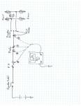
A quick check you can do with a multimeter (or 12V lamp)
With the key on, unplug the flasher, is there 12 V on one terminal
If No check Fuse F7
If Yes and none of your 4 flashers light up no matter where the switch is the chances are its in the switch.
Its quite easy to pull the switch apart but be carefull not to loose any of the small parts. Once you have it apart turn on the key and short between the center terminal and either of the outside terminals with the key on if the flashers go the fault is in the switch.
You can also check for voltage on the center terminal.
I doubt it.s in the wiring from switch to flasher lamps, it would be quite unusual for both sides to go at the same time.
Keep us posted.
Roy
-
Guys, thanks for your help. I disconnected all the battery connections, cleaned them, cleaned all the relays, the connection to the starter and the fuses and the bike started right up. Must have been either a loose connection or some corrosion. Thanks for all of your help.
Mike
Thats great news. To prevent future problems apply petroleum jelly (vaseline) to the terminals. This keeps the Oxygen from the metal so
that Lead Oxide cannot form. Lead Oxide is a hard light grey insulating layer that mostly forms on the negative terminal.
I learned this trick as an apprentice working on large traction batteries.
Roy
-
I like the approach, but I would suggest that you add a means for measuring the altered signal as well. Then the changes you made could be quantified and you would know what numbers mean what.
Yes, you could easily measure it but that makes it more complex.
The idea was to set the pot for best performance then square it all away later
e.g. measure the mV with the throttle closed, remove the circuit and set the sensor to give the same mV
I haven't tried it and probably won't get a chance for a while (next riding season)
Regards
Roy
-
I like it, Roy. Kudos for your ingenuity and resourcefulness.
Thanks Rachethack, I will remember your advice. I don't worry about that sort
"What upsets me would kill most people"
I woke up in the middle of the night and thought perhaps +/- 750 mV would be a bit extreme
so I revised the circuit to show a series resistor to drop the voltage down to about 0.5
Regards
"I have to figure out this file attachment thing eh"
-
Hi,
I am very new on this forum but I spent my working life troubleshooting electrical and electronic equipment.
Seeing all the posts re Throttle Position Sensor I was wondering if anyone has tried adjusting the mV on the fly.
The simple circuit attached would cost pennies and allow you to raise or lower the mV while riding to find the sweet spot.
Once found you could then tweak the position sensor and remove the temporary circuit.
I would just solder the two components directly to an AA cell and tape it to the bars. The battery would last several
days with the components shown.
What do you guys think?
Revised sketch
Note re revision
In hind-site the original sketch would have too many mV so I have added a 1K resistor in series
with the battery, this will reduce the mV from +/- 750 to +/- 250
You could add a switch which will eliminate the offset when open and perhaps add a scale in mV
to check the operation just connect your multimeter to the wire in and the wire out.
None of the component values are critical. It is only intended as a temporary addition.
-
I have been lurking for a while on here since I got my 2002 LeMans this past spring. I have just replaced the pawl spring and buttoned everything up. I went to try and start the bike (heard the fuel pump go through it's usual noise) and just got a click and then nothing. Checked the starter fuse and it had blown. I tried a back-up 15amp fuse and got the same. Looked at all of my connections at the battery and can't see anything amiss.
FYI, the battery is new and kept on a battery tender. All relays were replaced in April of this year with the ones from Motratech. I can't see any insulation missing from any wires where there could be a short, but does anyone have any ideas to try or places to look for the potential problem before I start trying to pull too many things apart? Thanks for your help.
Mike
I assume you mean the fuse went when you pressed the start button, The only thing after the button is the clutch switch then the start relay.
What is the number of the fuse that blows (fuse position from front of bike)
Have you had any of the electrics apart recently?
Roy
-
I think the relay's get a raw deal. my bike showed all signs of crook relay's, went to auto electrician and he checked thre relay's , they were fine accept for the odd loose case however I bought 5 new ones and replaced them anyway. 8 mths later same problems, the fittings that the relay's plug into are crap and a high quality replacement is on the cards

I found thet the 5 pin relay is a direct replacement for the 4 pin. My relay bases are the variety with slip in spade connectors. It's possible to slip these out by releasing the clip with a small nail so they can be replaced or squeezed with a pair of pliers to tighten them up. I will smear a little vaseline on the prongs before I put them in, this makes them easier to pull out and helps prevent corrosion.
Roy
-
I just recieved a set of 5 relays from Digi-Key, $4.60 each. The postage to Canada $11.75 total US$34.70
I suggest you try to combine with a friend to cut down on postage
My V11 has 2 SPDT and 3 SPST but I elected to go with all SPDT
The 5 pin relay will replace the 4 pin relay without any wiring changes.
The relays appear to be the sealed variety
G8HN-1C2T-R RATED 20A for normally open, 10A for normally closed
www.digikey.com
http://search.digikey.com/scripts/DkSearch...p;x=17&y=14
Roy

-
Has anyone tried varying the throttle position mV while riding?
It seems to me an easy thing to make up a pot to allow offsetting the mV +/- say 20 mV
This would allow you to stop and move the sensor by an equivalent amount.
Just a thought

Roy
-
these guys have exactly what you are talking about - Super Bright LEDs -
# 74 is a direct replacement LED bulb for the 2721 wedge bulbs on the V11s. (bottom of the page) I purchased the T1.5 lamp with holder - T1.5 lamp - and with some tweaking to the holder it fit right in. (bottom of page) I bought red high power ones and they look great on the instruments. very cool, with build in resistors and diode make them fool proof. dirt cheap too! cheers. a.
That is brilliant Arek, if you'll pardon the pun, did the indicator for the flashers work ok as well.
I think the lamp color should match the colored mask that sits in front.
I guess I will have to find another winter project

BTW, have you tried out the low fuel light, in my V11 Sport I think it's a thermistor that requires a certain load. The lamp may need a resistor in parallel to supply this.
Did you replace the Spedometer & Tachometer lamps also?
Regards
Roy
Update - I ordered a bunch of lamps from Ultra Bright will update you once installed
-
Well, I would not be very surprised if someone sells LEDs with standard bulb socket and has built-in serial and parallel resistors as well as polarity-correction diodes to exactly match a good old bulb. It would be dirt cheap to mass produce, and they would hardly ever break. But I haven't seen any. I must admit I haven't looked for them either. If I stumbled upon such a beast, I would seriously consider trying it out as long as it wasn't ridiculously priced.
I will take this on as a challenge, this sort of thing is what I do for a crust.
I have been messing around with the idiot lights on my V11 and had the same thoughts as David.
The bi-directional current for the direction indicators is not a problem, a bridge rectifier will fix that.
As I see it there are two options,
A) Insert LEDs into the existing sockets and wire the required matching resistors to the lamp-holders.
 Remove the existing lamp-holder base and make a printed circuit board with all the LEDs and resistors etc. on it.
The advantage of A) is it would be adaptable to other light cluster patens.
I will start experimenting with the different styles of LED available
Regards
Roy

-
You could try overhauling your starter e.g. new brushes and bushes. If the bushes get too worn there is a possibility that the armature is rubbing somewhere. Starters are quite simple or just take it into an auto electrician.
I think the voltages you see are pretty reasonable.
Roy
-
Cuan,
That's a great story.
Like you I just fell in love with a VII Sport.
I doubt I will be able to turn it into a beutifull creation like yours
But I will love it just the same.
Regards
Roy
Tekno Saddlebag Fade
in How to...
Posted
Hi,
A set of Tekno saddlebags came with my V11 Sport, These have faded in the sun to sort of light purple colour.
Does anyone know how to restore these to Black.
I cant seem to find who makes these, does anyone know manufacturer, web site etc.
Thanks in advance
Roy