All Activity
- Past hour
-
Mea culpa: I just realised I didn't do the math to the end here I've corrected myself there, and here
-
Mostly for helping myself to understand the circuit and the suggestions for troubleshooting, might be of help to others. If someone sees errors, I will correct them.
- Today
-
HEY HEY HEY . I'm not smart enuf to do that !
-
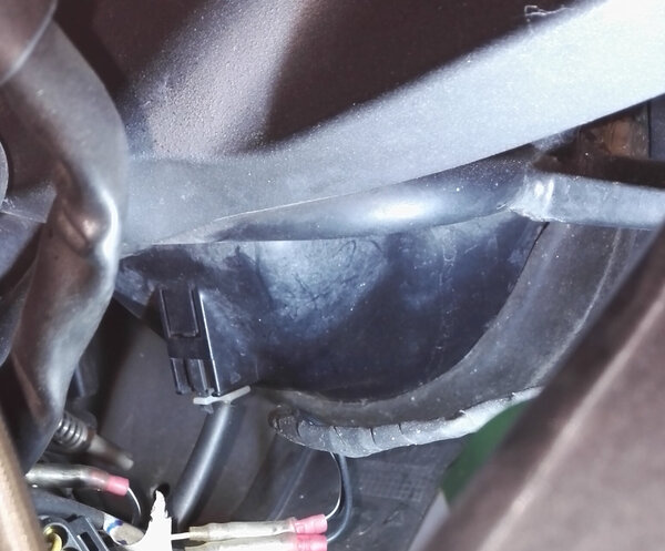
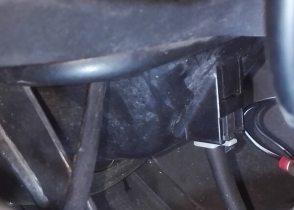
SamP , did you reconnect the red/green wire to the V reg ? Also , there should be continuity between the 2 pin connector consisting of a blue wire and a red/black on the regulator wiring harness of the bike wiring harness.
-
Let's talk batteries, @Sam P. Did you replace the "destroyed Odyssey" with another Odyssey, or something else? A voltage loss from 13.0 to 12.7 in an hour is not a good sign for an Odyssey. There are specific parameters to "condition" the Odyssey that may help contribute to a solution. "trickle chargers"/ "tender" are known to be damaging to the Odyssey battery unless the voltage is adequate, yet will not "charge" the Odyssey with sufficient amperage (at least 6 amps).
- Yesterday
-
Here is the @Kiwi_Roy rendition ( hosted on @Weegie's dropbox ): https://www.dropbox.com/scl/fo/no8adkie1sl6frnc2qmm8/ALzrUXsngCqMRtfMR1cXedE?dl=0&e=1&preview=Guzzi+Wiring+-+Simple.pdf&rlkey=8x5byzd4ux3107610i22ig5v6&st=3xbx7rbu
-
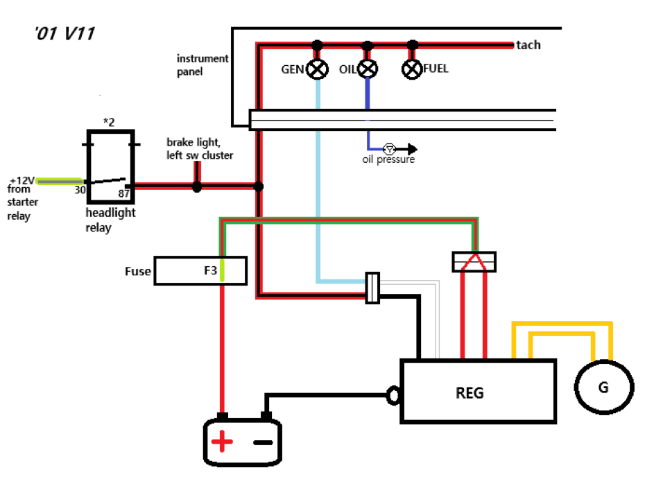
No concrete reccomendation, I'm afraid. What @gstallons was getting at here was to check for continuity from where the power that makes the warning light go on, the output of the lighting relay, to the wire after the warning light that goes into the regulator, where it is switched to earth by the regulator when the charging system isn't working. As far as I can tell, you did measure between the correct points, and saw 15 Ohms. There is a light bulb in that circuit, the warning lamp, so the resistance wont be zero. Apart from that, the wires themselves will have a resistance, albeit very low. Whatever, maybe the 15 Ohms are ok. Without knowing the wattage of the light bulb, it's guesswork. Thinking about it, if one assumes slightly ratty connections, and takes a couple of Ohm away from the light bulb for that, the wattage for the light starts heading towards 1.5 Watt, which is plausible, I think. EDIT: the maths were wrong. I just went back an looked at it again, and realise that in fact there is a total of something like 9.6 Watt being generated. That is, I reckon, actually too much for a warning lamp, so probably the lamp itself plus some ratty connections. I still suspect that there are two perhaps unrelated issues here, i.e. the weird business that the charge warning lamp only comes on at high revs, not at key on engine off, and the indications (never more than about 12,3 Volt at the battery) that the system is never charging, not only not charging at high revs. As @docc mentioned further up, the fact that the oil light doesn't go on at key on engine off is also weird. The oil pressure switch is a simple switch that opens when the oil pressure rises. Therefore, it also must light when the ignition is turned on, until the motor is running. As far as that goes, maybe there is indeed a bad connection in the dash somewhere. Both of those lights get their power from the same source, via connector #8 on the wiring diagram which is most likely the 12 pole Amp connector you mentioned further up. Without saying it is the only way to go, I would personally want to know that those warning lights are functioning the way they are intended, and would focus on that first. The reason being, if the charge warning light is doing unexpected stuff, it may be masking the charging problem (but not causing it!). On the other hand, if the supply to that light is not solid, that may affect the regulator. I would expect the regulator to overcharge in that case, but don't know for sure if it really would. EDIT: forgot to mention... The next thing I would do at this point is measure the resistance (Ohm) from the input for the blue wire on the regulator (not the wire itself, the connector on the regulator) to ground. Firstly key on, engine off, then at various motor speeds. It should be open (almost zero Ohms) without the engine running, and closed (very high resistance) with the engine running. What happens there when the engine hits the engine speed at which the light has been coming on would also be interesting.
-
I will look it over.
-
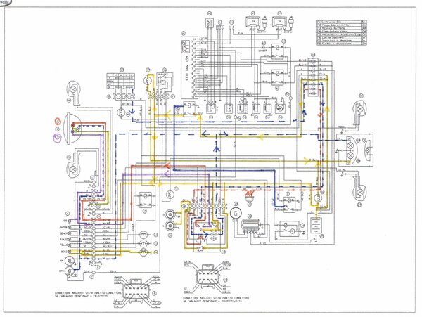
From Carl Allison [ @callison ] on thisoldtractor . . . What is not correct on this diagram is the the reference/warning circuit wires from the regulator are white and black then change, at the flat "SAE" connector, to blue and red/black. https://www.thisoldtractor.com/guzzi007/pdfs/1999_V11_sport.pdf
-
Did someone post a correct wiring diagram for this bike ?
-
" recommendation for next steps " . . . For starters, I am going back over all of the outcomes. Like @audiomick, I suspect a high resistance problem (bad/corroded connector) in the mix. I suspect this is in the "voltage reference"/warning light wiring. The oil light issue may be a clue. @Sam P, can you pull the connector from the oil switch and ground it (KOEO) to see if the oil light illuminates?
-
Absolutely ! SamP forgive our zeal but we want you to get this fixed and operating correctly. Moto Guzzi will make you an electrical tch whether you want it or not !
-
I think: cigars all around. I cannot imagine another online community with this much enthusiasm dedicated to helping another member solve a problem.
-
I have said this once before. I think EVERY V11 has their own wiring harness and ign. key.
-
Give that man a cigar.
-
Just an addendum: the turn signals are on their own circuit.
-
The oil light , gen light and low fuel light are connected to the + terminal of the tach (I assume it works ?) , the front brake light switch (does it work?) , turn signals (do they work?) and rear brake light switch(does it work?)
-
I am trying to follow your analysis, which I appreciate, but do you have a recommendation for next steps? Perhaps I missed this.... Thank you in advance!
-
It means there is a resistance in there somewhere, but I think you know that. If my maths are correct, that would mean something is generating 0.8 Watts. That is, I reckon, to low for a light bulb, unless perhaps it is a small LED. Assuming there are no LED's involved, I'd be more inclined to suspect a bab connection, or maybe an incorrect measurement. For a good connection, I'd expect it to be less than 1 Ohm. EDIT: the maths were wrong. Not 0.8 Watts generated, but rather 0.8 Amps flowing. That means 9.6 Watts, which is too high for the lamp in the circuit, I reckon. So the 15 Ohms is possibly a light bulb plus a bad connection or two. It means the multi-meter is seeing the same resistance in all of its ranges. Up until 2000 Ohm, the resistance is big enough to register properly. In the 20kOhm setting, the meter is still seeing it, but rounding the actual 0.015 off to 0.01. In the 200kOhm setting the resistance is no doubt still being measured, but is too small for that range to appear on the scale.
-
Just cleaned up the connection, and re-tightened the ground wire. Turned key on, headlight and neutral light come on, but still no oil pressure or battery light.....
-
If the probe from the multi-meter wont go in, stick something in that will fit and measure off that. A paper clip, maybe...
-
You've mixed up terms there. You're not measuring current, that is the amount of electricity that is flowing at a point in time. You're measuring voltage. That's the "electrical pressure", correct term "electrical potential", that is present at that point in the circuit. You're quite right to consider whether the volts are being pushed in from the regulator or are coming from the battery. That is the correct question. The fact that the voltage is not changing at any revs indicates that the regulator is not "pushing volts into the battery". If it were, as has been mentioned further up, the voltage at that point should go up to around 14V at higher revs. It isn't, so the volts are getting lost in the regulator (it's malfunctioning) or not getting from the regulator to the battery (bad connection).
-
I think you have that the wrong way around. As far as I can tell, the black wire between that connector and the regulator feeds the 12V reference from the red-black wire into the regulator, and the white one is the connection from the warning lamp(blue wire) into the regulator. The voltages coming into the connector from the wiring loom should be close to the same as battery + at all revs. If the voltage coming in from the red-black wire deviates from battery + too much, the regulator will think the battery is not being charged and put too much voltage out on the feed to the battery. A "wrong" voltage on the blue wire coming into the white wire to the regulator should not be able to cause the regulator to malfunction. EDIT: I see @docc has already said that here:
-
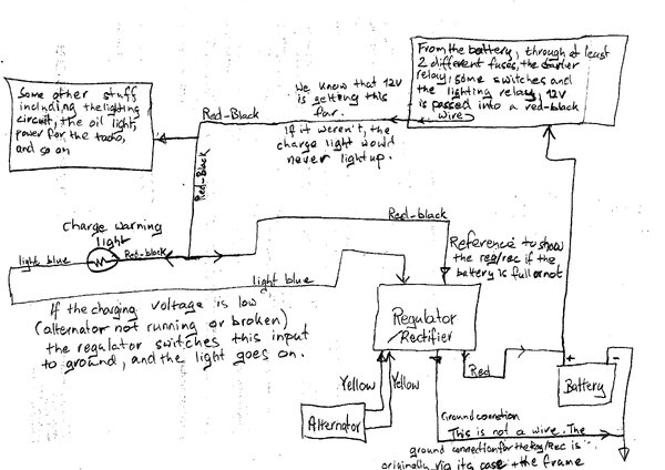
@Sam P I was away over the weekend. Reading over what has been posted in the last couple of days, it seems you don't always know why you are measuring what people suggest. I made rough and simple sketch of the charging circuit, in the hope that it will confuse you even further maybe help a bit. Hope that helps you understand what is going on.
-
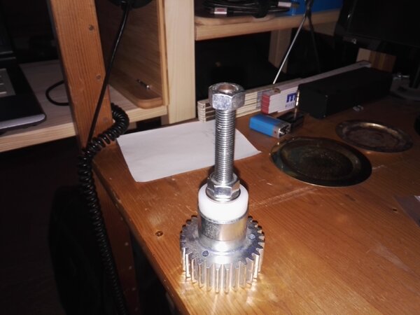
Roller tappets
-


![IMG_20241123_224923[1].jpg](https://www.v11lemans.com/gallery/monthly_2024_11/small.IMG_20241123_2249231.jpg.e096b44fe99686a032b551bbf1bb4264.jpg)
![IMG_20241121_231155[1].jpg](https://www.v11lemans.com/gallery/monthly_2024_11/small.IMG_20241121_2311551.jpg.6d864d972198380bf13530b1452c1fe4.jpg)
![IMG_20241121_000827[1].jpg](https://www.v11lemans.com/gallery/monthly_2024_11/small.IMG_20241121_0008271.jpg.962c0c739eb00d312e5a0276a23c0ba7.jpg)
![IMG_20241121_000723[1].jpg](https://www.v11lemans.com/gallery/monthly_2024_11/small.IMG_20241121_0007231.jpg.64fd80bfcf5580bc577fb0575af3326c.jpg)