

Rolf Halvorsen
-
Posts
121 -
Joined
-
Last visited
-
Days Won
3
Content Type
Profiles
Forums
Events
Gallery
Community Map
Posts posted by Rolf Halvorsen
-
-
Lucky Phil
I have a new gearbox house if you need.
Rolf
-
I might also have the "small" parts that you need. Let me know and I can make a list of what you need and what I have.
-
Hi Pete(r)
I happen to have the recall kit GU973260900016. It consist of 2 sleeves and 1 redesigned cush drive. Let me know if you have trouble getting these parts free from Moto Guzzi.
Send me your mail and you can get pictures of the parts.
Rolf (rolf.halvorsen@mail.com)
-
 1
1
-
-
Correct assembled Helicoil thread is the simplest and best way. When you insert it deep enough, it will prevent to be unscrewed. The top surface will not be changed.
-
If one (by mistake) remove the positive cable from the battery before the negative - it is very easy to touch the ECU with the wrench. Thereby the ground wire from the ECU (directly, but hidden to the negative battery pole) will "be burned" and since the original ground wire is put together with a lot of other cables in a cable loom - all will be partly damaged.
The solution is easy. Disconnect the original ground wire from the ECU (which leads to the negative pole on the battery) - and replace it with a separate wire "in the open". So if someone later tries to remove the positive cables from the battery -and touching the ECU, without first the negative - the new open wire will get burned alone - and all others will be safe.
Rolf
-
2
-
-
Maybe we all have the wrong focus.
The transition resistance between the sensor-pins and the cable - might be where we should focus.
The ECU measures the resistance only. from about 4.0 KOhm (cold) down to 0.4 KOhm (warm). 100% contact = 0 Ohms.
To measure resistance you will require a relative low voltage to be sent.
A low voltage combined with corroded pins - might give you a higher resistance NUMBER than it should be. Telling the ECU to think the engine is colder than reality - and feeding more fuel than necessary.
Am I into something here?
Rolf
-
Since this sensor should act as an oil temperature sensor - the oil inside the head should transfere the temperature to the surrounding aluminium (in the head). Let us consider this to be ok.
Then the aluminium (head) (after being cooled by air) should transfere its temperature to the copper metal base of the sensor bracket. This should also be ok.
Then the temperature of the copper base should transfere the temperature to the brass sensor - with an air gap?
The best insulator in the world is - nothing (vacuum).
Then comes air (dry).
Next is any fluid material. (Water can evaporate - so you cannot use that.) Any fluid oil should work, but a very thick oil substance (grease) would be better. I think any grease will work fine since the distance is around 1mm level. Specific thermal grease - or whatever you call it - should not be needed, even if it technically is better.
Any comment?
Rolf
-
As I can measure - there is an air gap inside between the sensor and the holder. There has never been a heat leading paste inside the ones I have worked with. And why is the original made of partly plastic?
Plastic insulate better than brass in a housing. Would a brass house leak heat away?
Rolf
-
Marty: PERFECT, thanks.
Here is an interesting article from Murray (Down under) posted May 22, 2007
After just playing with one to find out its not the problem The "engine oil temp sensor" which is acutally the head temp sensor and has little to !@#$ all to do with the oil temp. What makes me say that I have a bike that has an additional temp sensor in the oil cooler and the reading out of that are radically different to the head temp sensor. Is a NTC (negative temperture coefficent) themocouple with a range of -40 to 170 ish degrees celcius. NTC means as the temp goes up the resitance goes down resitance at 10 degrees is around 3.7K ohm and at 80 degrees is 0.37kohm. Buy rights you should be able to bung a 10cent resitor in there and run home on that if it fails. The sensor does not earth through the cases oil preasure switch style but has a return line to the ECU. Hope this helps NB all temps are celcius/metric.
-
1
-
-
I think Guzzi calls it the oil temperatur sensor.
-
Thank you Marty for your responce. It is the engine head sensor (mounted in a plastic house on the right cylinder head.
Do you hav any specific data for this? I had if on a bench (not touching) . About 20 degrees Celsius.
Rolf
-
A friend came by today complaining that his bike (Quota) seems to be running too rich when warm.
After a little discussion - and since I had a new sensor, we decided to switch sensors. But before we did this - we measured the resistance of the new sensor to be around 2.3 KOhm (cold). After switching - the bike seem to run better, and my friend is happy. (who and where can you find a new sensor when you need one?)
The old sensor measured about 3.8 KOhm (cold).
Can anyone tell me what the resistance values of good sensor should be? (I intend to buy a new and perform measurements on it.)
Rolf
-
Fantastic. They arrived today. 2,5 days USA - Norway. Now I am back in business helping Guzzi injection drivers. Rolf
-
2
-
-
I ordered 50. Let us see how and when my parcel arrives.
Rolf
-
 1
1
-
-
Thank you Docc and Mikko
I just ordered 50, and the order seems to go through.
I was happy with my first 50 -so I just want to have more available.
Thanks again.
Rolf
-
1
-
 1
1
-
-
Hi all
One year ago I purchased 50ea. relays from Mouser. No all are gone to my friends in Norway.
Now I find that they are obsolete.
Can you give me the name of alternative relays?
Rolf
-
The original is article number: 01763030
Teo Lamers (tlm.nl) has these.
Rolf
-
Thank you.
This document is the best I have seen - ever. I am soooo pleased.
Rolf
-
I remember reading that that sensor should measure around 650-700 ohms between + and + pin (3pins version).
But I have forgotten where I read this. Can anyone help me? Would like to copy that article.
Rolf
-
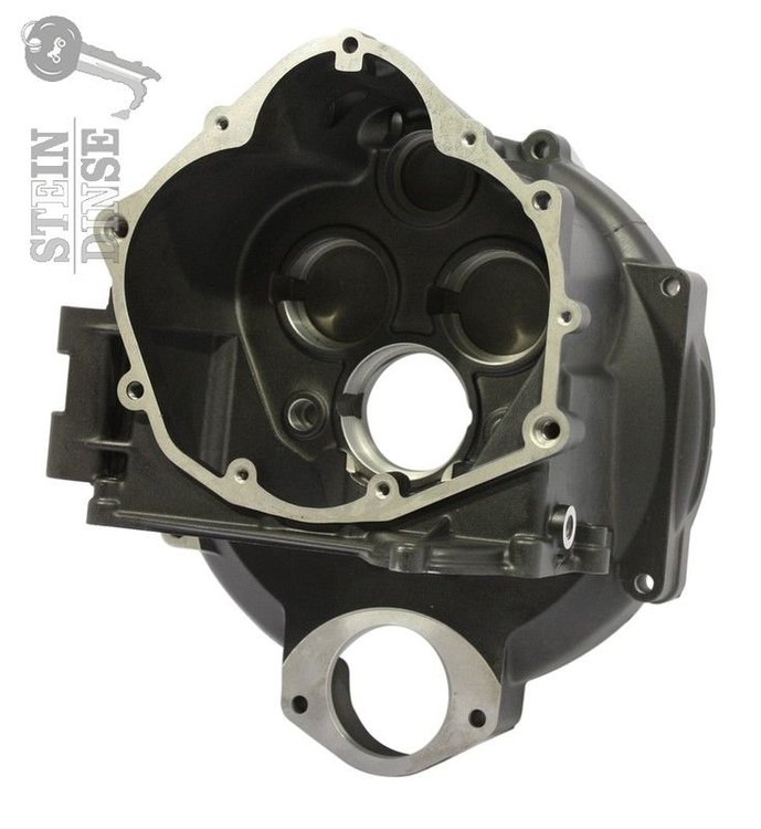
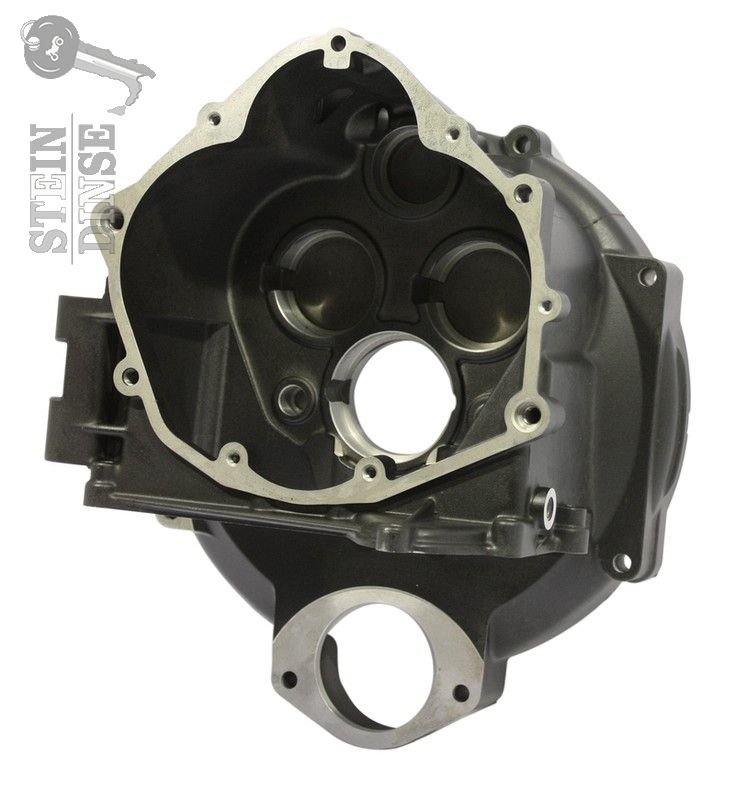
Ok I misunderstood. My 2001 Rosso Mandello had a single plate clutch which they called RAM. This version had a aluminium flywheel that had some problems. I changed to 2 plate clutch to be om the safe side. I know that there is other type RAM clutches on the marked. The clutch hub boss on the 2005 gearbox is the 2 plate clutch version.
If others are interested in my parts - let me know.
-
1
-
1
-
-
To build a double plate clutch - you need the following parts:
6 - M8x25 hex screws in hardness 10.9 (black)
6 - Special washers
1 - Flywheel 04067000
10 - Springs (5 - 04084100 and 5 - 13084100)
1 - Pressure plate 30082900
1 - Push rod plate 04082800
2 - Friction plates
1 - Intermediate steel plate
1 - Ring gear 01067930
8 - M6 screws with washers
1 - Clutch boss connected to the gearbox 0421160
(I happen to have almost all of these parts new, but since I live in Europe it will be some shipping cost. Let me know in a PM if you want to talk about buying my parts.)
Rolf
-
2
-
-
Yes you can use the 2005 gearbox - and you have to change the clutch to double plate since the clutch-boss on the 2005 gearbox is designed to use this.
-
The thin earth cable from the ECU to the minus on the battery is inside the wire loom together with a lot of other thin cables. When I got my V11 Coppa Italia - someone had tried to undo the positive main on the battery. By doing so - he (she) made contact between the battery positive and the ECU - leading to high current floating through this thin earth wire - leading to melting down all wires inside the wire loom as Kiwi-Roy shows in his picture. I repaired all the damages and made a new ground wire from the ECU to the minus OUTSIDE of the wire loom. Thereby I can let this outside wire melt without damage to the others. I recommend everyone to do as I did.
-
2
-
-
This is copied from another place:
(EDIT/May 2019): Having had two TPS go bad after 50,000-62,000 miles/ 79.000-100.000 km, it is simple enough to check the TPS when it is hooked up to the DVOM (Digital-Volt-Ohm-Meter) . Switch the DVOM to resistance in the 2000 Ohm range with the key off. Slowly and smoothly open and close the throttle body and observe for a smooth transition of increasing and decreasing resistance from the potentiometer (TPS). If there are jumps and glitches or drops and variations in the resistance, the TPS should be replaced. Be certain to set the DVOM back to > DC voltage < before baselining the TPS in millivolts or you'll think something is terribly wrong!
I have both analog and digital multimeters. I would think that the analog version would be better to read. Anyone have tried this? (I will try with both instruments in a week or 2).
Rolf
-
2
-
Which year models.....?
in Technical Topics
Posted
Pete
I found out how to put the picture in here.
Rolf