JuhaV
-
Posts
99 -
Joined
-
Last visited
Content Type
Profiles
Forums
Events
Gallery
Community Map
Everything posted by JuhaV
-
Any comments to these ignition issues ? br, JuhaV
-
Hi, See http://wbo2.com/ and there, for example, "the miniature 2CO sensor". With a wideband lambda probe you need some special electronics to interpret the sensor signal. Coarsely, the cost of the above mentioned system seems to be 250 AUD for the box, 80 AUD for the probe itself and 180 AUD for a digital display. I do not have any experience myself with these Tech Edge products, but have not heard anything bad about them either. I am considering to get one when my budget allows me to do so. Ok, but because we now seem to have the fuel measuring side more or less covered and the debaters have digged deep into their current positions, why not switch to the ignition timing issue ? The basic question is : How do I optimise the ignition timing for a given rpm & load condition ? What shoud I measure ? How is the A/F going to affect my ignition timing and vice versa ? The only very basic adjustment that I have done so far is to back of (retard) the ignition timing in those operation points where I experience pinging. Is the optimal setting close to the pinging limit ? How about knock sensors ? Do you have any experience on those ? It would be nice to have both lambda and knock sensor on the bike to give feedback both the the fuel and ignition map adjustments. br, JuhaV
-
Hi, It seems that we have gone quite chemical in this threat I am just thinking aloud below in order to understand this gas issue a little bit better. In practise the only measurable gas on the road seems to be oxygen, because there are no practical gas sensors for the other important gases. The main problem when measuring CO is that in those infrared cells the gas needs to be in controlled temperature and without too much water vapor. Those will namely interfere with the CO absorption spectra and ruin the measurement accuracy. This means that CO measurement can not be done in situ in the exhaust channel. Therefore, CO measurement is done by sampling, which inherently leads to slower response. If we go back to the combustion chemistry. We put in into cylinder air (nitrogen N + oxygen O) and fuel (hydrocarbons CxHx, i.e. hydrogen H and carbon C in diffent combinations). Out comes different things in different combustion situations. Perfect, stoichiometric combustion would produce only water vapour H2O and carbon dioxide CO2, because the fuel and air are in correct ratio and all fuel will be burnt. Nitrogen goes mainly through without chemical reactions, a small amount forms nitrogen oxide NO, which is harmfull but nowdays removed by the catalyser. Fuel rich combustion produces carbon monoxide CO in addition to CO2, because there is not enough oxygen to fully oxidize (burn) all carbon to CO2. So, CO indicates rich mixture. And what is important here is that CO is a combustion product, which means that it is truly produced in such combustion where there was not enough air reacting with the fuel. In other words, if you see CO in the exhaust it for sure means that some part of the combustion is taking place too rich. Fuel lean combustion produces hydrocarbon emissions, because some part of the mixture is too lean to burn at all and can cause even misfire. Also, in this case there is residue O2 in the exhaust, because there was not enough fuel to use up oxygen. Why O2 is not perfect to indicate the status of the combustion process. My understanding is that it is because O2 is not a combustion product. In other words, if you see O2 in the exhaust you cannot tell for sure that this O2 has been even trying to participate the combustion process. It might be there because of exhaust system air leaks or travelling throught the cylinder without ever "meeting" hydrocarbon molecules" to oxidize. The combustion phenonema inside the cylinder is not homogenous and happens very rapidly, therefore the chemistry may not have time to go all the way through to the equilibrium values ? The inhomogenousity means that the are always leaner and richer spots inside the cylinder, especially in these Guzzi engines Even if we but in fuel and air in perfect ratio, because of the non-ideal mixing the result will not be perfect. Hope this is doing any sense. br, JuhaV
-
Terve Pexi, You truly have given at least me some headache with your high level starting post Okay, short term and long term trims ? If I interpret your mail correctly I think that you are referring to well developed automotive ECUs (maybe Alfa Romeo ?) that have the capability to "learn" and also to store what they have learned for future purposes. Therefore, in the long term they are able to refine the fuel map that then becomes the "base map" according to my very non-official terminology This base map is then used during a driving situation and short term trim is applied on those base map values based on instaneous lambda probe readings. I do not know for sure, but I would speculate that those ECUs that are nowadays found in production motorcycles are not able to do this kind of long term learning. In other words, when ever you turn of the power, the ECU is left with the original base map. The base map will not evolve automatically over time. You need to "chip", "tune boy", "powercommand" or "cliff" your ECU very actively to change that map. According to my best knowledge, the only gadget that is able to do this is Cliff's Optimiser, which is a separate tuning & display tool connected to a My15/16M ECU. Did this sound anything like what you meant ? br, JuhaV
-
Yes, that is the case as we both know I was only trying to indirectly point out that the road and race conditions are rather different and especially with the 2-valve Guzzis, we are limited well below 8000 rpm which makes it even simpler for the modern electronics to cope with. I am running closed-loop all the way to the red line (set at 8500 rpm) without problems. It is true that the lambda feedback is not perfectly instaneous because of 1) the delay in the lambda sensor response to sniff the exhaust, and 2) the ECU's response in acting based on the sensor reading Let's assume now very realistically that for item 1) the delay is 0.2 s and for item 2) the ECU checks the situation 5 times per second. These values are practical even with the existing probes and ECU electronics. What this means that in a fast changing situation (rapid rpm & throttle change upwards after some steady state driving) in the worst case I am running solely based on the base map because the closed-loop system is not able to make any changes to the fuel injection. Then, if the "situation" remains there even for 1-2 seconds, the closed-loop system is able to tune tune the fuel injection towards more appropriate value than what the base map can provide. The tuning steps may be, for example, a few % of the map value and they can be recalculated 5 times per second. What happens then when the throttle is closed ? It will take a similar amount of time for the closed-loop system to tune the fuel injection "back" towards the original map value, or whatever the value should be. If we prevent that the lambda feedback is not allowed to tune the fuel injection to become overly lean (or rich), then according to my understanding in those situations where the closed-loop is not fast enough to act we just kind of "drop" back to using the base map. On the other hand, in normal situations (maybe 99 % of the time) it takes only less than 1 second to adjust the fuel injection to optimum. The only truly limiting factors here are the lambda probe response time and accuracy. JuhaV
-
Cliff, The rest of the reluctant open-loop (but maybe not so open-minded) world will follow your lead eventually, but maybe it will still take some time. I still take it to be a huge oversimplification to simply state that closed-loop is no good, because there are so many different ways closed-loop feedback can be applied. And the lambda sensors are also becoming better and faster day-by-day. For example, if closed-loop is not applicable in very fast accelerations (as kind of argued earlier in this threat), when the throttle is opened quickly in excess of a given measure, it is quite simple to write down into the ECU software a condition that in this case closed-loop is not applied. Such a condition could hold, for example, 0.5 seconds and after that the ECU may revert softly back to closed-loop mode. So, was this open-loop or closed-loop use ? The engine could easily stay 95 % of the time in closed-loop mode and spent the rest of the time in open-loop mode. A good base map is needed even with the closed-loop system, but the closed-loop can fine tune that map to be as perfect as possible in changing engine, weather, gasoline etc. conditions. BTW, I need really to check if it is actually the closed-loop that prevents me hitting 15000 rpm with my Sport br, JuhaV
-
Hi, Putting in new pistons and wanting to optimize the squish band height and also to safety check the valve-to-piston clearance, could you advice me what is the best method to accurately measure these dimensions ? I am thinking of using some soft material on the top of the piston and then rotating the crank by hand. Afterwards I just check how that stuff was squeezed between the engine components. But what is the best material to use for this test ? Any other methods that have been found practical ? br, JuhaV
-
Thanks Dlaing, I myself think that all others are limited either because of the software or hardware, but Cliff is the only one who masters both sides. So, in principle he is free to make whatever is needed if he is just motivated to do so. And we should remember that he is propably also the one who has but most of the development work specifically towards the Guzzi engine. I bet that there are many who would be interested to see what is inside his code. TuneBoy and Cliff share the same island So, why not do some work together to make the perfect ECU-hardware / software combination. Even the wide-band lambda sensors + electronics are available from down under, so in this case I keep looking towards that direction also in the future. I am running closed-loop practically all over my map without any ill effects at all and at the moment relying on not-that-perfect narrow-band sensor. I use the sensor at its rich "edge", where the accuracy is not perfect, but still it gives me better results than without the feedback. br, JuhaV
-
Hi, There seems to be several approaches available to these ECU issues with each of them having their pros and cons. However, I would like to draw your attention again to this closed-loop versus open-loop issue and try to take a little look into the near future. Sorry for the lengthy submission, but you know, it is winter now here in Finland If you see, for example http://www.forparts.com/BoswidebandO2.htm, you can appreciate that the 02 sensors are under continuous development in the similar manner than also all other things in this technical world. The traditional (narrow band) O2 sensors, that can be today found in most of the cars and some motorcycles, give only a rich-lean indication. They can't tell the computer the exact air/fuel ratio. Further, their response times are rather slow (>> 0.1 s). This means that they are mainly good for slow response fine tuning of the mixture: Every time the oxygen sensor's output jumps or drops, the engine computer responds by decreasing or increasing the amount of fuel that is delivered. This rapid flip-flopping back and forth allows the feedback fuel control system to maintain a more-or-less balanced mixture, on average. In other words, they are most useful in steady state conditions the engine running with steady rpm and throttle. This situation is to be heavily avoided by any sportish bike rider having some self-respect BUT, and here is the interesting stuff, the newest generation of oxygen sensors is a totally different story ! They are already available today with the price going down all the time when they are installed in a growing number of new cars that need to meet the ever more tightening emission regulations. These sensors are being called "wideband" lambda sensors or "air/fuel ratio sensors", because that's exactly what they do. They provide a precise indication of the exact air/fuel ratio, and over a much broader range of mixtures - all the way from 0.7 lambda (11:1 air/fuel ratio) to straight air. For example, Bosch LSU 4 wideband oxygen sensor has a response time of less than 100 milliseconds to changes in the air/fuel mixture. The price of this sensor is somewhere between 50-100 US dollars depending where you buy it. Because of its nature, the sensor requires a separate control unit to provide the sensor certain reference voltages and in order to interpret the current signal that the sensor outputs (see for example, http://wbo2.com/). After a couple of years, I think that most of the new cars have these wide-band units instead of the narrow-band sensors. Alltogether, this means that already today you can plug into your exhaust a very accurate and fast sensor to tell ten times a second how your mixture was. Yes, I used there the past tense, because the 02 sensor always lacks behind and it is the ECU that needs to make clever forecast what is going to happen next. That requires intelligent software but it is possible to do. Now, what means then “closed-loop”. Let us define that open-loop means no feedback from the exhaust to the computer at all. Then there can be “full” closed-loop or “partial” closed-loop. Full closed-loop could be defined to mean that fuel injection is fully calculated using the lambda sensor values without any kind of fuel map. I do not know if such systems even exist. Partial closed-loop requires some further definitions. Do we mean partial map closed-loop or partial adjustment closed-loop. Sorry, I have made these terms up just to clarify the difference Partial map closed-loop means that in some parts of the map the computer performs closed-loop adjustement to the mixture and in some parts of the map the system is in the open-loop mode. This seems to be the case in the newer Guzzis, where the map is open-loop above some rpm & throttle values. Partial adjustment closed-loop means that the lambda sensor is allowed to cause only a certain amount correction to the injection values, let’s say plus/minus 15 %. The base values are taken from the map. Further, there can be different O2 target values for different parts of the map: multi-target closed-loop ? Based on the above, I would like to say that it is a rather huge understatement to say that closed-loop is not useful in motorcycles ! Even today, we can have a wide-band 02 sensor in the bike and use that info to fine-tune the fuel injection at the rate of ten times per second. If this is done by further defining different 02 targets for different parts of the map and then allowing, for example, 10-15 % adjustement for the map values, I would say that this is useful beyond steady state riding. There are also even today some acceleration pump simulators available for the ECUs, and these can be made to better predict the fuel injection “future” based on the “historical” data from the throttle position, rpm and 02 sensor. Further, by using separate 02 sensor for each cylinder, the fuel injection could be individually adjusted. Even further, a knock sensor could provide similar tuning possibilities to fine tune the ignition timing in real time. My feeling is that when these possibilities are there, it means that instead of dyno tuning our bikes once or twice, in the near future we kind of carry the dyno with us all the time and shift into continuous realtime tuning. A dyno will be an instrument to define the base map, but the closed-loop operation is the key to have a perfect map all the time. Many seem to think that 02 sensor is there only to meet the emission standards and therefore we are better of without it. At least for me, the 02 sensor is there to ensure that I get maximum performance out the engine all the time Br, JuhaV Sport Corsa 1100i * partial map and partial adjustment closed-loop with My16M * wide-band 02 sensor and multi-target closed-loop to be included
-
This is most interesting ! Could you kindly inform us how many map updates it is possible to do with one TuneKey ? It seems that your edit program requires such a key and your web site sells them also separately. Therefore, it seems that map modifications "consume" these keys ? Did I understand it correctly ? br, JuhaV
-
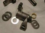
Thanks Pete, It seems that K-lining is the way to go. The benefits seem to be logical and the material is better than the material of the original guzzi guides. Luckily there are many mechanical shops even here in Finland to provide that service so no need to ship the heads abroad. Because the heads and valves are now in the focus, the next question is what to do with the rocker arms that have slight marks on the sliding surfaces contacting the ends of the valve stems. My preliminary approach was just to carefully restory them by grinding with fine emery paper to get a fresh smooth surface. Then I found this picture : Does anyone know if these are commercially available somewhere ? It looks nice even though a bit heavier than the original. Good Start for the Year 2005 for all of you ! - JuhaV
-
Hello, For the valve guides one option is K-lining them : K-Line at Cylinder Head Shop I think that these "inserts" are rather widely used both in car engines as well as motorcycle engines. Anyone having guzzi experience about these ? I am considering to try these out myself in my Sport. br, JuhaV
-
Thanks, I picked up some of the following stuff from there. Might be interesting also to some others. Here it comes ... BACK-CUTTING VALVES : Flow gains can be achieved by back-cutting the exhaust valve. However, the lip on the exhaust side does serve to impede flow reversion--we've already discussed that. Back-cutting the valve 30 degrees (right) relieves the valve of its flow impeding ridge (left). The result--a significant gain in low-lift flow at all levels of modification, and virtually free horsepower. The stock intake valve has a lip backing the valve seat face, which acts as a ski jump to the airflow on an engine where the airflow predominates across the back of the valve. The first step was to remove this lip with a 30-degree back-cut to the valve. Traditionally, a high-performance Wedge, three-angle valve job is performed with the stock 45-degree seat angle, with a 30-degree top cut and a 70-degree bottom cut. While the production seat angle on Chrysler engines is 45 degrees, a properly done 30-degree seat often can pay big dividends, in terms of low-lift flow. Because of the geometry involved at low lifts, the 30-degree seat will open more area to airflow for the same amount of valve lift--this can provide an advantage. Switching from a 45- to a 30-degree seat can be done only when the valve size is increased. Low-lift exhaust flow is significantly enhanced by grinding a radius in the exhaust valve’s margin (arrow, right). This can be done by hand with a grinder, with the valve chucked into a drill press or lathe, and turned at low speed. In fact, back-cutting on the exhaust valve helps improve flow in both directions. So, as much as it helps low-lift flow out of the cylinder, it will promote undesirable reversion when used with high-overlap performance cams. Since exhaust flow from the cylinder is what we are after, looking for improvements to the exhaust valve's profile is not quite the same as with the intake. To help exhaust gas flow around the face of the valve, and outward back across the seat, putting a radius on the valve margin is successful. The radius margin brought low-lift flow back into line, to the tune of a 14-percent improvement at .100 inch over the out-of-the-box big valve. PORT WALL SURFACE : A fine grinding stone can be used to blend the rough surface left by the cutter. Further polishing can be done with the sanding roll. Although the effect on airflow is insignificant, the rougher surface helps promote the boundary-layer turbulence desirable for keeping the fuel in suspension. PORT VELOCITY / PORT SIZE : Implicit with higher port velocity is the notion that the air column is moving faster. Basic physics tells us that a body in motion (in this case, the air column) will build momentum and will want to keep moving in the same direction, even as the force acting on it is removed. In the case of the air within the port, the force acting on the air column is the pressure differential in the cylinder as the piston moves down. When the piston slows as it reaches the bottom of the cylinder at the end of the induction stroke, good port velocity is helpful to continue filling the cylinder, due to the air column's inertia (especially if there is good low-lift flow, as the valve is now closing more quickly). In the exhaust port, many of the same considerations apply. While here, we are not drawing air in to fill the cylinder. Maintaining good velocity helps to scavenge the cylinder of spent gasses to promote good cylinder filling of fresh air/fuel charge. Consider an oversized exhaust port with poor flow velocity. In this situation we have a large, slow-moving tub of burnt mixture hanging around just outside the valve. As the piston reaches the top of the exhaust stroke, lack of inertia in our lazy, oversized port can allow the spent gasses to stop, and actually reverse direction during the overlap phase of the valve timing. This creates dilution of the fresh mix. This effect is progressively worse at lower rpm, where flow rates and velocity are at their lowest. Increased overlap with high-performance cams magnify the problem. The result--an engine that is slow to get on the cam as rpms pick up velocities in the port, and poor low-speed operation. The bottom line: Both the intake and exhaust ports must balance flow velocity and flow capacity to achieve flexible performance over a broad range of rpms--a necessity in a street performance engine. We should maximize the efficient use of the port to achieve the required flow, instead of simply making bigger ports. SQUISH BAND : If the area between the flat face of the head and the piston top is sufficiently close, as the piston reaches TDC on the compression stroke, the mixture that occupied the area over the piston is forced at high speed into the direction of the advancing flame front. The net effects are faster burn and greater turbulence at the time of combustion--advantages for efficient combustion. This is the squish effect. A second benefit is the mechanical resistance to detonation is improved when a closed-chamber head is used with a close piston-to-head clearance. Detonation begins at an area other than the main flame front. With a flat-top piston, the area opposite the spark plug in the quench area is prime detonation territory. If this area is sufficiently tight, the ability for it to detonate reduces since the combustion at the desired flame front occurs quicker (squish effect), and lessens the time for heat rise in the mixture at the far end of the chamber. Furthermore, the thin section at the squish area exposes only the small volume of mixture to an equally high surface area, diminishing the heat rise in this part of the mixture. br, JuhaV

-
BrianG, If you check the price of My15M versus the right part of that "equation", you will be very happily surprised Closed-loop is nice to have and useful, especially because you can decide where in the map you want to have it and where not. Ignition adjustments will be also useful if you are ever going to make any mechanical mods to your engine. My15M will give you also this possibility without any extra cost. I like to have everything adjustable ! br, JuhaV Sport 1100i/My16M
-
Thanks Pete and others, Now, when the valves are off from my heads I could use some advice how to perform some mild porting stuff by myself with my Dremel Any pics available from those who have ported heads in their engines ? There must be some basic things that are reasonably easy to do and do not require severe removal or adding of material from the channels ? I am after some kind of "blueprinting" type things just to fix those small issues that usually are there in these "non-japanese" product-line engines. Yes, I know that I could take my heads to an expert, but it is more interesting to learn something by doing even if there is some possibility to go a little wrong. The valves and guides will be replaced with something else than original Guzzi parts. br, JuhaV
-
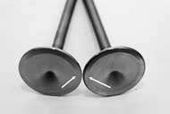
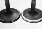
Hi, I just removed the heads from my Sport 1100i -98 with 33000 kms on the clock. The valve guides and stems are so to say "gone". The valve stems look exactly like that shown in the pic posted by John T. I would estimate that there is about 0.08 - 0.10 mm clearance between the stems and guides which is clearly too much. I believe that V11 and Sport have both the same type of valves : inlet 46.5 mm and exhaust 39.5 mm. This seems to be also confirmed by Guzziology. Now, it seems that the material both of the guides and valves is way too soft. There seems not to be too much sense to put in new original parts if there is reason to believe that Guzzi has not done anything to fix this problem ? Do you know any other source than Mike Rich for new valves and guides made of better material than the original ones ? Don't want to say that he is not a good source, because I think that he might actually be the best one, but I would still want to know what are the possible options here. By the way, the bike did not smoke or consume oil or express in any other way that the situation with the valves was that poor. That is quite interesting ! br, JuhaV
-
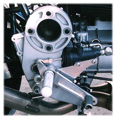
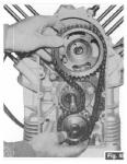
Hi, Sorry, this might be a slightly Sport 1100 related thing, do not know if V11 uses the same type of tensioner. My question is : Is it possible to change the cam chain tensioner without removing the sprockets and the chain ? Can I slip the the tensioner away from behind the chain somehow ? I would like to avoid opening the sprocket nuts if possible. I believe that the chain and sprockets are still ok after about 30 000 km. In my earlier bikes I have used the aftermarket longer curved and spring-loaded tensioner instead of the original type. Any idea which type works better keeping the chain tight. Any comments appreciated. See attached (poor quality) pic for more details. br, JuhaV
-
Hi all, I made some fuel pressure measurements in my Sport 1100i and they showed that I seem to be running slightly low with original regulator: 2.8 bar instead of spec 3.0 bar. During the winter I will install an adjustable fuel pressure regulator and do some testing in the pressure range 3.0 - 3.5 bar. I have fully adjustable My16M ECU so it is easy to match the map with the modified pressure. I think that raising the pressure from 3.0 to 3.5 bars should not create any leak problems etc, because this change is anyway reasonably small. There should be larger safety factor than that build into the fuel system components. I'll have an pressure gauge installed permanently in to the cockpit so I will be able to monitor how the fuel pressure behaves in different driving situations. I am especially interested to see if there are any pressure drops at full throttle. My first experiments with the gauge showed something like this, but because those were made revving the engine at neutral and not driving on the road, I'll need to make further tests on the road to check this out. If there are any fuel pressure fluctuations, it will be quite hard to create a "perfect" fuel map, at least without any kind of closed-loop control. By the way, I believe that the lambda-probe response time is in the order of tens of milliseconds, so closed-loop system is capable of correcting very fast phenomena. This means that closed loop, if correctly applied, can help also during accelerations, not only during steady state riding conditions. br, JuhaV
-
Yeah, Anyway, it would have been an "all show - no go" type mod. Thanks, JuhaV
-
Thanks Luhbo, I visited the Techedge www-pages and it really seems that if one needs reasonably priced wideband sensor that might be the way to go. Your first impressions confirm that they have decent products with nice price/quality ratio. I think that it might be possible to program their lambda system to give out 0-1 Volts, but if Cliff will provide 0-5 V input range for the sensor in My1XM that is even better. Techedge seems to also offer some miniature version especially for motorcycle use. It does not have those datalogging capabilities but with My1XM you don't really need those, because the ECU can be used to do the datalogging instead. br, JuhaV
-
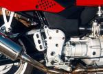
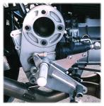
Hi, Does anyone know are those older and newer model "peg plates" for a 1100 Sport interchangeable ? It seems that the new model has at least one extra hole in the upper corner to hold the rear chassis. I usually don't do any purely cosmetic mods, but I really like the more technical look of the old plate over the newer one. Any idea what the part numbers would be ? br, JuhaV PS. One of those pics shows an interesting peg mod with the brake cylinder relocated.
-
Thanks Todd and Jeff in Ohio, I suppose that the gas analyzer could also be something more advanced than just a lambda probe ? If the dyno is a load-cell type dyno, then I believe that the bike can be held at steady state to find out perfect settings for each load & rpm situation. Sounds good. A reasonable amount of test points around the map should provide very well tuned map. If the tuning software is clever enough, it could also make part throttle accelerations (to simulate real life situations ) to find out the best settings to serve both steady state cruising and accelarating. Need to find out the closest Dynojet Tuning Center to me br, JuhaV
-
I vote for Pirelli Diablo (even if mine have those chicken strips ) br, JuhaV
-
Very good question indeed ! I will also throw in here my "old" question : How do you adjust your map correctly in the mid range (partial throttle) if you are using an inertia type (not brake type) dyno ? I still have the impression that inertia type dynos simulate mainly the full throttle acceleration situation. Please advice if this is not correct interpretation. BTW, more advanced ECUs allow the user to decide what parts of the map are used in open-loop or closed-loop mode. The most advanced ECUs even allow to key in different lambda targets for different parts of the map. br, JuhaV
-
Hello Hubert, Yes, the wideband sensor is much better, but sofar I though that it would be also very much more expensive. 250 EUR does not sound very bad, even if here in Finland I can get a new 4-wire heated narrowband sensor from a car parts shop with 45 EUR. Please, share your impressions with us when you get the Tech-Edge sensor. br, JuhaV