al_roethlisberger
-
Posts
4,482 -
Joined
-
Last visited
-
Days Won
21
Content Type
Profiles
Forums
Events
Gallery
Community Map
Everything posted by al_roethlisberger
-
Ahhh, I wonder if one couldn't just pry off the "cap" on the 6-speed breather, then put a hose on it? al
-
Paul, apologies, but I didn't quite get what you meant by saying "the swingarm thing is the way to do it" ...can you explain further? And, could you possibly post a photo or describe in more detail how the 5-speed vent uses "a piece of rubber" to seal the vent instead of what the 6-speed units have today? I'm very interested in this as well. thx al
-
...I've actually been on vacation over two of the past three weeks. While I honestly haven't been sitting in front of the PC, I do come in from the garage, etc... and peck on the computer for 30 minutes or so here and there. The rest of the time though, I do leave the forum logged on at work as I sit in front of the computer all day.... and I'll check-in for a few minutes every hour or two between meetings and such. But honestly, even though I'm logged-in, I'm really only checking it out a handful of times a day. ...or do I protest too much al
-
Yeah, I bid once... just so I could say "I did" I doubt I'll pursue it though, as it's getting pretty pricey(...what, about $140USD now??). We'll see though. I think it would be a great item to get for the Forum, then auction again to our folks to support more file-space, etc... al
-
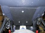
The finished version will extend another inch or two further to protect the shock, etc... Also, in the photo it appears that the plastics dramatically do not match, but in more natural light, the add-on piece is nearly unnoticeable, and it's invisible from any angle other than looking up under the fender. BTW, it uses all stock bolt locations. The bolt through the tool-tray and battery-tray simply have to be longer. Both of these are an afternoon's job... and that's if you take it slow. Very simple. al P.S. The measurements are 7.5 inches wide(at the widest) with a 1/2 inch indentation about 6 inches down. The length of the mock-up is 10.5 inches, but I think the final piece will be about 13 or 14 inches as long as it clears the shock/swingarm linkage.
-
Also, I've been disappointed from the start from the rear underfender, and how it ends right before the battery tray. This leaves several cables/wires exposed to debris, as well as just looking unfinished. And with the OEM hugger removed, a little extra protection for this area and the shock would be a good idea. So I had a little more scrap ABS lying about and this is what I came up with... This is the first mock-up:
-
Another angle:
-
You may remember a thread some months back where many of us were trying to track down the cause/source of clouded transmission fluid. After some investigation, it was determined that most likely culprit was water intrusion through the transmission breather located at the back of the transmission. Although the V11 has a fender/hugger, there is no fender or barrier to debris directly behind the transmission(in front of the tire). So when riding through water, etc... this is slung almost perfectly at this fitting from the rotating tire. While several fixes were discussed, the easiest seemed to be the installation of a triangular piece of plastic in the front of the swingarm. It proved nearly invisible, and should protect the rear of the engine/transmission. So, since my bike was already apart... I went down to TAP Plastics and picked up some ABS. I cut a triangle about 10.5 inches wide, and 5 inches tall, with a cutout for the shock linkage at the top. I used the same "conduit hangars" as I used for me PCIII mount, and it seems to be a really good fit. Following are some photos, although it's a bit hard to see once installed... which I guess is a good thing BTW, I'm liking the look of the rear without the OEM hugger. I might leave that off for a while

-

Intake Mods: No "Lid" versus Pods
al_roethlisberger replied to al_roethlisberger's topic in Technical Topics
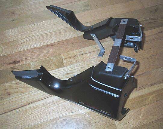
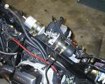
A clearer photo of the kit all put together after final adjustments:
-
Here is a photo of the initial mock-up:
-
...my concerns too, but then again if there's particulate matter in the filter, it came through the pump And, somehow I don't think MG gave THAT much thought to the placement and orientation of these, especially since the pump has been moved around to three different places in the V11 history so far(not counting the new in-tank solution). Anyway, I've got my first mock-up put together tonight... and there's still TONS of room under the tank where the airbox used to be ...maybe I'll have to have a custom tank made one day. I bet I could get another gallon of fuel in there easy. al
-
Interesting, as this is opposite from how it's installed on my bike from the factory. As delivered from the factory on my bike, the inlet is on top, with fuel flowing "down" the filter. But your theory sounds reasonable, and is how I would end up mounting it in my new scenario. thx al
-
..no kidding, several of those are pretty stout solvents, some of which could make short work of some plastic bits and hoses. I would be cautious in regards to concentrations. As an example, a looooong time ago, I was working on my old FJ. I was trying to "clean out" the fueling system with that "B-12 Chemtool" stuff by adding it to the tank. I believe it is Toluene based. Anyway, something happened where I wasn't able to complete my project, and the bike sat for about a week with this stuff in the tank and fuel lines. It eventually ate the fuel lines, and unbeknownst to me... flooded my garage(well, 4 gallons of flooding) with the solvent/gas mixture. It actually melted a plastic trash can it ran up against. I didn't find it until the next day or two, and was very very fortunate I didn't hit the garage door opener, or the flourescent lights while the fumes were the most concentrated..... BOOM... bad stuff. Anyway, this case was obviously "user error" on my part, but indicative of how dangerous this stuff can be if not careful. I am much more circumspect now when working with these solvents. ...in the end, all was fine though. I got very lucky that it didn't eat off the paint, or gum-up the carbs.... or the worst, blow up my garage! al
-
So, with my "ingenious" (ah hem ) pod and air-box removal with side-cover retention thing.... I now have the opportunity to relocate the fuel-pump somewhere, say... on top of the spine, to get it away from the heat of the cylinders. There are some questions though. I am planning on mounting the pump on top of the spine, below the filter, where the airbox used to be. There seems to be plenty of room for this, so placement shouldn't be a problem. Although I do have to fabricate some sort of bracket. I plan to orient the pump with the inlet at the bottom, and the output facing up toward the filter. This also should be a "good thing" as it is the same factory orientation with which the pump was mounted before, and keeps the inlet at about the same or lower level as the petcock, which should allow for proper head pressure, gravity flow, priming, etc. Here's my question though... Since the pump will be directly below the filter, I plan to turn the filter around so that it's input is almost nose-to-nose with the output of the pump. Will the now inverted(inlet bottom, outlet top) orientation of the filter pose any problems with filtering, etc? I wouldn't think it would matter, but I thought I'd ask. As it stands now, the filter's input is on top, and flows "down" before exiting to the injectors, etc. This would be reversed if I flip it over. BTW, as an aside, while removing the pump, I noticed that the inlet has a small screen/filter. I removed it to check it for debris, etc... and while blowing it out did indeed notice several small granules of debris that it caught. Remember that this is before the high-pressure filter, and after whatever screen the petcock has. I wonder if an inline filter between the tank and pump inlet might be a good idea. If so, this could be a cheapo plastic filter, as this link from tank to pump is not pressurized. I'm pretty excited about getting rid of the airbox, relocating this pump, and reorganizing some of the harnesses and hoses. I think this will really clean up the area under the tank/spine, and increase air-flow=cooling for the bike With the airbox, and tangle of hoses/wires as delivered, it was quite messy and dense before. I suspect this is not how the original designers envisioned it... I also found a great local source for heat-sheilding fabric "tubes" that can be put over wires, hoses, etc. They are just like the stuff that came OEM on my FJ, and that stuff was great. It's some local "speed shop" that also sells all sorts of neat hardware that may find their way onto the bike. And I went by TAP plastics and got some black poly-something-or-other scraps for free, and made the fender that Mike?... or was it Lex? ..made to sheild the shock, trans breather, etc... from debris. It's a simple triangle, more or less, 10.5 inches across the bottom, 5.5 inches high, with an inch and a half wide length chopped off the apex(so it looks like the Great Pyramid) to clear the shock mount. I'll post a picture later. ...now if I can just find somone that sells the AMP Superseal connectors, I'll be set for completing "all current projects" ... ok, well other than the dual-plug saga al
-
1) What does one do with the oil breather line that attaches to the top banjo fitting up by the headtube on the spine(right in front of the tank), that attached to the OEM airbox? Obviously this is to recover oil vapor, etc... from the spine. With the airbox removed, I'm not sure what to do with this hose. 2) I assume the air-pressure sensor that was installed in the airbox can just be mounted anywhere? ...or is there a more ideal place? thx! al
-
Question: Would a 5mm drop in the front suspension make a BIG difference in handling, or not? I hoping "not", and I ask because the Cycle Cat bar risers will probably require that for their installation. al
-
Interesting: Octane and Water Injection
-
Intake Mods: No "Lid" versus Pods
al_roethlisberger replied to al_roethlisberger's topic in Technical Topics
Hi Rudy, Well the pods I have are the newer models that have the "intake runner" already integral to the pod, as opposed to older pods that were simply cannister/cylinders that clamped onto the intake. These filters have a about a 4 inch "runner" already molded into the filter, and have the runner angled such that the filter can be appropriately angled and adjusted to fit correctly by simply rotating the filter around. The part number is: RU 1780 Very nice, but pricey, filter. I'll be fine-tuning and cleaning-up the installation tonight and tomorrow, and then I'll post some final photos. I think that for what I'm looking for, this will work very well. I was surprised how well it turned out if you want to know the truth ...after all, it was just a "weekend hack project" that I was pretty sure would just end up being a mess, and I'd go back to my stock airbox with no lid al -
Good Mounting Location for PCIII
al_roethlisberger replied to al_roethlisberger's topic in How to...
Yep, that's felt The bumpers from the seat were rubbing the coating off of the frame, and I didn't want to end up with rust/bare-metal spots after a couple years like I had on my FJ. So I stuck some "heavy duty" felt on there. It works OK, although I have to press it back down sometimes, and after a while it wants to "creep" from the seat moving around a little. But it seems to be doing it's job. al -
Good Mounting Location for PCIII
al_roethlisberger replied to al_roethlisberger's topic in How to...
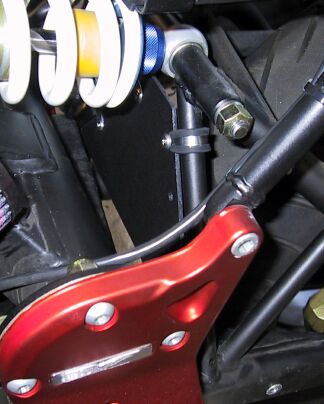
Yeah, I think that's what the package said, "conduit hangars" But bottom line, they are just cheapo pipe brackets from sheet metal, with a rubber lining. I found them in the electrical section, but they could be in plumbing too I would bet. al -
Good Mounting Location for PCIII
al_roethlisberger replied to al_roethlisberger's topic in How to...
No, that would be one drawback if one wanted to get to the manual adjustment buttons, or somehow wanted to remove it "easily". You cannot remove the PCIII with the tail-section installed. However, I figure once I get the custom map set, I won't be fiddling with the manual buttons or need to remove/move the PCIII around. So my only concern was making sure one had easy access to the serial port. Also, I can get my rear carapace off in about 2 minutes now, so it's not a big deal for me in any case al -
Good Mounting Location for PCIII
al_roethlisberger replied to al_roethlisberger's topic in How to...
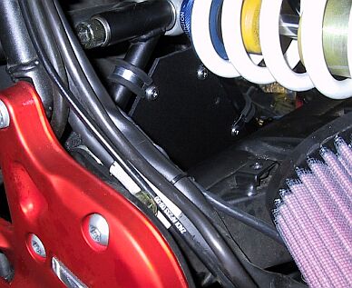
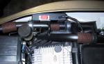
From a slightly different angle: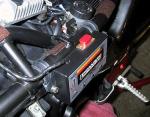
-
Good Mounting Location for PCIII
al_roethlisberger replied to al_roethlisberger's topic in How to...
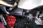
A better look at the installation itself: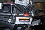
-
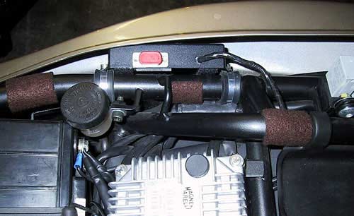
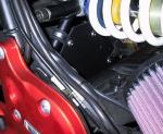
I was looking around for a good place to more or less permanently mount the PCIII on the LeMans. But since I have a pretty full tool-kit in the tool-kit area, and I do use the tail "cubby" for ad-hoc items on trips, etc... I didn't want to have to just lay the PCIII in either of these locations. So after looking around, I found that the PCIII will fit quite well mounted to outside of the seat subframe on either the left or right side, between the frame and rear plastic carapace. I simply used some 3/4" metal conduit hangers, with rubber protectors. You can find these at any hardware store. In combination with some stainless M6 bolts and lock-nuts, it was an easy and tidy solution. Here are some photos:
-
Intake Mods: No "Lid" versus Pods
al_roethlisberger replied to al_roethlisberger's topic in Technical Topics
I'll post some photos tomorrow night of the whole cover assembly off of the bike so you can see more clearly how it's attached and built.