vuzzi
-
Posts
106 -
Joined
-
Last visited
Content Type
Profiles
Forums
Events
Gallery
Community Map
Everything posted by vuzzi
-
The 1800 rpm was suggested by mr bean. The exact rpm is not that important. Most important is that you use a small throttle opening, cause only than you can measure small differences. Indeed a bit strange if you read different voltages. Some difference (10 mV) is not that big a problem. I think you should be able to feel it at the lh side (at the adjustemt wheel) if the linkage is sloppy. I'd say unbalance at idle should be corrected with the idle screws. The bypass screws should be set equal, that is, both half or both full turn out. I noticed too that engine breaking is much less with idle at 1100 rpm. But maybe that is a good thing for the drivetrain. Coughing and sneezing, and even blowing an intake rubber of is terrible. Good balance helps, and also equal valve settings. After my bike had the heads off and got new gaskets, my bike blew the intake rubbers of after a 30 km ride. Back at home I found that the intake valves were 0.1 mm of at one side. After adjustment the bike run as normal. Looking forward to setting the bypass screws and all that in spring. Right now my bike is under a cover with 10 cm of snow on top....
-
I prefer to set the throttles at the same angle by closing the air bypass screws, and than using the synchronisation rod adjuster at 2500 rpm. in that way you know throttles are not influenced by the air bypasses. Once the throttles are synchronised, the air bypass screws should be opened. Both equally. As I tried to explain in this topic, the air bypasses have different effects at different throttle angles. Air bypass and throttle angle can not be exchanged just like that. Opening the air bypass at one side more than the other will lead to uneven mixture and thus uneven running of the cilinders, namely at small throttle angles. Idle speed should be set with the idle screws at the bottom of the throttle bodies.
-
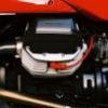
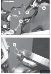
Opening the bypass screws indeed adds more air and increases idle speed, but this is compensated by closing the throttles (compare left and right throttles in the picture). This is done by backing off thhe small hex screws at the bottom of the trottle bodies. In this way the total air flow at idle can be kept constant. Turning back the small hex screws at the bottom decreases the angle of the throttles and results in a smaller voltage read by the tps. The tps can however be offset by the two small hex screws at the top of the throttle bodies, making the tps read 525 mV and making the cpu think the throttle angle is (still) 3.6 degrees. The offset angle affects the whole range, but in the end turns out to have a bigger relative effect on small throttle openings -> less air flow at the same mV reading of the tps or at the same throttle angle for as far as the cpu knows.

-
The mixture should stay the same at idle, since the tps is adjusted to 525 mV, indicating 3.6 degrees opening for the cpu. The flow data is interesting. It shows an even steeper relation between throttle angle and air flow. This might be because the relation between angle and air resistance in not liniear either. Edge effects play a large role in the resistance and since the total edge increases to a lesser extend than the opening as the opening gets bigger, so the edge/opening ration gets smaller. I asume this supports the effect of a richer mixture at small throttle openings. But I guess it 'd take a specialist in airodynamics or a hydrologist to fully figure that out.
-
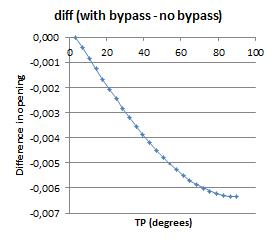
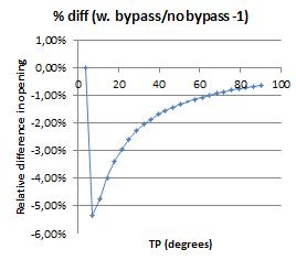
In several topics poor running at low revs and small throttle opening have been adressed. I too have been working on the tps setting for this reason. I like the set up according to mr bean (http://www.v11lemans.com/forums/index.php?showtopic=13188&hl=Micha&st=0): Step one - Set your valves to world settings Step two - Set your bleed screws to open 1 full turn Step three - Synch throttle bodies at just off idle (around 1800 rpm) Step four - Set idle to 1100 using left idle screw adjuster only Step five - Set TPS to 3.6 degrees (I forget what that translates to in mv..someone here will know) Step six - Ensure idle trim is set to zero I noticed he adviced to open the air bypass screws a whole turn instead of half like the manual. I have been wondering what the effect would be of opening the ait bleed scews to a greater or lesser extend to the mixture. So I tried to figure it out using my basic high school maths. This is what I did: I calculated the opening of the of the throttle, starting at 3.6 degrees, using the cos of the angle. This is not a liniear relation. See first figure. I then added 20% opening through the air bypass in another column in my spreadsheet. Opening the air bleed screws results in a bigger opening and higher revs. This must be corrected by decreasing the angle of throttle, while setting the tps back to 525 mV, making the cpu think the nagle is still 3.6 degrees. The result is an offset of the opening which has a bigger effect on the total opening (throttle + air bypass) at bigger openings. See second figure. However, in relative terms, the effect is different, namely a reletively large difference at small openings and a small difference at large openings. See thirth figure. In the example I simulated a bypass opening of 20% of the throttle opening at idle. This results in a 5% smaller opening for the air flow at small trottle angles, and thus a richer mixture. The exact numbers are not so important, but most important is that by opening up the bypass screws the mixture in general gets richer after correcting the tps, namely at small trotle openings. It may help against backfire and poor runing at small tp and low revs Too bad it's winter now, but I'll experiment with it next spring. I hope all is clearly written down and maybe some of you have better maths skills than I have and can check this. Any thoughts are welcome. looking forward to reading them


-
The ball valve (not being there) does not seem to be the problem cause I took off the breather hose. There is still fluid in the intakes. I suppose it is oil. At least it feels and looks like it. Defenitely no water. Fuel? I don't know if that can be on such hot intakes. Would evaporate. Or could it be droppng from the injectors after the engine cools down?
-
the problem is that she uses 1,5 litre of oil on 1500 km, resulting in carbon deposits in the combustion chambre and an empty wallet.
-
Well, this story needed an update. I have taken the heads off. Checked: - the piston rings, piston and cilinder: very good condition. Almost like new, apart from the carbon deposits on the piston - intake valve guides - valves: thight, no exessive play. Only carbon deposits on the intake valve - exhaust valve and guide: slight play on both sides when valve is at max. open, maybe due to overheated head. Carbon deposits on valves too. - all the valve stems are still like they are brand new. No wear. - the engine breather hose is still off the air box. Checked all hoses from and to the engine: all OK Since the heads were off I had the exhaust valve guides replaced. Also all the carbon deposits are removed. After refitting the whole bunce I went for a ride. The bike runs fine like before. I then checked the intakes again by taking the manifolds of, I noticed there is still oil in the intakes and on the valves. So since the breather hose is off, where can this oil still come from? - past the piston rings? Might get less when I lower the Oil level. Might get less when I run the bike in again since the cilinders and pistons have been off? - still between the valve and the guides, although they are thight? - between the guids and the head??? I can't see any other options. Any ideas anyone?
-
Before I start dissembling my bike, where is the ball valve? I took al look al the parts manual and the workshop manual, but there doesn't seem to be a ball valve?
-
In my case I guess it's an oil issue and not a fuel one, considering the oil on the intakes (both sides) and the deposits that still look wet. In case the breather system is not working properly, could the presure in the engine increases the presure under the rocker covers (through the cannels that normally let the oil run down) , pushing oil through the valve guides? Somewhere else I read decelerating on the engine breaking power with closed throlte causes extra vacuum in the cilinders 'sucking in' oil through the valve guides (I know, pete, as you wrote somewhere else (topic on oil pump), there is no such thing as suck, it pushed by the gass preasure on the other side of the valve guides, and I agree). Driving style may have an effect too in this way. I already took the hose from the spline to the airbox of and send it to a small bottle. I hope to find out soon what the effect of that is. As soon as I get a chance (next wednesday I guess) I 'll clean the ball valve and the spline. If the problem remains I 'll have to look for a place to get the k-line in.
-
k-lined: taken out and replaced. But by which ones? Are there any aftermarked valve guides? Any thoughts of the kind of italians cheese they are made of? There is a big difference between mozzarella and Parmesan. At least my girlfriend starts to show interest in my v11 for the first time now doing some research for me (see http://www.e-rcps.com/pasta/inf/cheese.shtml).
-
She has app. 20.000 km on the clock. Runs good, vibrates a bit, but not too much. I use the prescribed agip oil, but filled up with Q8 10w50 4t full sinth I bought at a highway petrol station on holyday (almost a litre now).
-
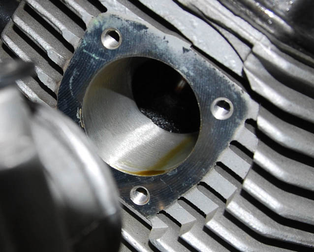
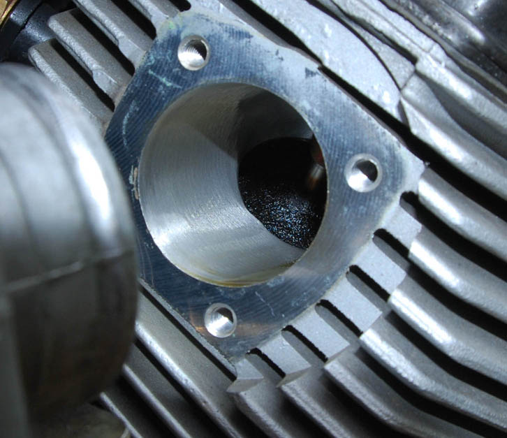
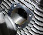
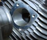
I noticed quite some oil consumption lately, say 1 litre on 1500 km. Having read the topics on oil consumption I took al look in the air box, which turned out to be just a bit moist from oil. I noticed oil on the intakes, between the injectors and the heads. Removing the intakes gave me a look at the intake valves (see pictures). They turn out to be black from carbon residues. I 'm a bit afraid this is caused by soft valves or guides. To be sure, I took the breather line from the airbox and lead it to a plastic botle to catch any oil, so any oil from the breather wont get to the intakes and valves any more. I just took as short 80 km ride, and haven't caught any oil in the bottle jet. I'll check the intakes after some more rides. In case the valves are bad, are they hard to replace? Does anybody have tips on what valves / guides should use to prevent this from happening again?
-
The CO is set by adjusting (correcting) the fuel input. Has your dealer reset the air bleeder to 0.5 turn? 1.5 is to much in my opinion, leading to a poor mixture at small throtle openings (at bigger openings it has less effect), and a poor mixture may lead to backfire. So I 'd check the air bleeder screws. Another cause may be unbalance. A bigger throttle opening on one side may lead to a leaner mixure at that side since the fuel quantities are equal. I have been fighting this myselve. It is pretty much allright now, but I still like to keep it running over 3000 rpm, although some situations make me go lower in revs.
-
Mine tends to backfire when hot as wel. I now have the TPS set at 175 mV at fully closed and 550 mV at idle, combined with 1/4th turn loose for the air bypass screw instead of 1/2. It makes the mixture sligtly richer and delays the ignition at 2000-3000 rpm and almost closed trotle. Runs fine that way.
-
The pipes were pressed in pretty much all the way. However, when loosening the clamps after a ride and hitting the joints a few times, the crossover moved back a bit. It would be nice to have the pipes and the crossover connected (held togheter) with springs in stead of thight clamps. I'll check the possibility of that at a local garage. For now, i'll press the crossover back on the pipes when hot, and that would do for now. Thanks for the ideas for now.
-
I had the head flanges fitted just so that the headers can rotate left-right in order to position the crossover in the centre. In that way there was a mismatch of just over 1 cm. I just bend the connection at the crossover a bit so there is only little upward presure. Parts are stock except for the muffers, but they don't have an effect on this matter. What should be the goal of loosening and retightening after heating the system up? Differences in thermal expansion between alu and steel?
-
Allright. But how much pressure should there be on the rubbers? Should it lift the crosssover up 1-2 cm?
-
OK, thanks. I'll start thightening from the headers. How about the crossover hanging in the U-bracket. Should it hang loosely or should it be pushed up?
-
I'm reassembling the exhaust system and run into some questions. First, I noticed that I have to push up the crossover (behind the gearbox) quite a bit in order to fit it to U-shaped bracket. So the bracket really puts some pressure on the exhaust system. I wonder how the bracket and the crossover should fit. Just loosely or pretty thight (pussing the cross over up 1 cm)? And how about the clamps. As thight as possible (say 30 NM) or loosely? Thanks for any help.
-
Hi, I took my swingarm of last week but forgot to measure the forks adjustment value (like the mannual sais on p. F40). Now that I'm reassembling the thing I don't know how deep to screw in the fastening dowles. Does anybody know how to determine depth for those fastening dowles (number C on p. F40 of the manual)?
-
Have you tried cleaning the starter? It worked well for mine. Take the starter out (better disconnect the battery first), take it apart, in some (most?) cases it's enough to clean the plunger. http://www.v11lemans.com/forums/index.php?...15235&st=0)
-
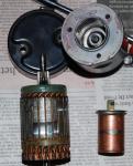
I took the starter off. Checked all the wires to the starter and starter relay. they seemed OK. I put 12 V on the sollenoid using an old and weak battery, and the plunger quite strongly pulled the bendix forward. Put 12 V on the starter engine, and it rotated nicely, though not as fast as i might have expected. Then took the starter apart. The sollenoid was slightly black and greasy at some points which easy to whipe off. The black and grease was not in a way that it would have made it hard to move, however, could if have some effect on electric properties? I noticed some wear of the copper layer of the plunger. Anybody knows if that can do any harm over time? After geasing some of the rotating parts I reinstaled the whole thing and it starter as never before. Still not 100% sure that caused the slow cranking, but happy enough do be driving again.
-
tha battery connections are allright I could try to fit the lucas starter of my v65. Are there any more experiences with alternative starters?
-
Mine had been a bit slow cranking. Today however she wouldn't crank at all. I tried a couple of times, (click was there and all, could hear her trying), but couldn't get it going. All of a sudden, at the 10th try, she cranked like never before. I was so supprised I forgot to open the throtle, so no start there. Next tries were no success and I had to take my car #@%$&@^$^. The whole situation indicates to me the bad solenoid. I'd like to try a new starter, maybe a mishubishi, but I 'd need to know what type to take. The ones from http://www.motoelekt.com/guzzistarter.htm are probably overpriced It 's probably a standard one, like: http://www.allproducts.com/ee/dahkee/13-mitsubishi-l.jpg However, no one seems to know what type to take There are some ewn ones of unknown brands on ebay as well http://cgi.ebay.com/ebaymotors/NEW-PREMIUM...151610006r31476 http://cgi.ebay.nl/Anlasser-Moto-Guzzi-V10...=item27a8f327fa Anyone has experience with those?