Guzzi2Go
-
Posts
411 -
Joined
-
Last visited
-
Days Won
1
Content Type
Profiles
Forums
Events
Gallery
Community Map
Everything posted by Guzzi2Go
-
Sport 1100 earth return path (and other electric things)
Guzzi2Go replied to greenman's topic in Technical Topics
Seems like your ground runs through the neutral switch. EDIT: Bad phrasing. Looks like intermittent short when neutral switch "kicks in". However, since the fuses stay alive the fault is probably in the powering circuit. Could a relay be disengaged due to neutral switch engaging? -
Spanish Inquisition
Guzzi2Go replied to Baldini's topic in Special place for banter and conversation
Bin Laden??? -
Done! But it took an OOOOOOMMPPHH!
-
OK! I am off to the garage to give it one more oomph!
-
Finally got around to have a go at the forks. Managed to open the right leg, but I am having problems disengaging the cap on the left one. Grabbed the blue nut and the top cap (just as on the right leg), but they do not budge. Should I take a bigger hammer or is there any other trick on how to unscrew the cap that I am unaware of?
-
That's it! Guzzi is a disciplinary measure, not a motorcycle.
-
Just for those that are interested. I did a bit of extra research trying to figure out what to do with the fuel level meter, so I connected a 12V power supply and 100 ohm resistor in series to the fuel sensor. Measurement shows that at -15 liters from the full tank, the fuel sensor swings from 500 ohm down to 100 ohm. At -13 liters it is still at 500 ohm, so it is not suitable for precise measurement. Works more like a switch. Also, here is a table for KOSO RX2N fuel meter. It shows dependency of the fuel level bar graph (10 bars) of the input resistance. No guarantee though. For some reason it was very difficult to tune the measurement in. I checked as far as I had the nerves and it seems to be ok, however... 10(Full) 0-50 ohm 9 52-60 8 67-82 7 86-118 6 122-145 5 157-210 4 232-297 3 347-464 2 524-820 1(Empty) 850-1000 Also, for the sake of completeness, the EOBD lamp now misused for alternator is lit when pulled low.
-
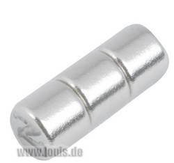
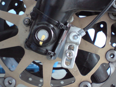
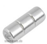
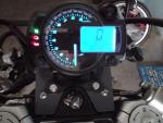
How to connect KOSO RX2N to your Guzzi (and live to tell about it) Recently I started going through speedo cables at an alarming rate, so I decided it is time for something electronic. Would keep it to myself, but since one of the forum members tried the same and asked some questions, here some info on how I did it. You may find it useful some day when your Vaguelia irreparably dies. But first a few words about the device itself. It comes in a nice box one usually packs children toys in. Be sure to open it before your children get impression it is a present for them. You will get the instrument, instrument and sensor brackets, speed sensor, two temp sensors (oil/water) a lot of wires, screws, and a fistful of snap-on wire connectors. The type that cuts through the insulation connecting two wires together. Pretty simple. So far so good. What you will need but not get are: sensor magnets, and the optional "L type speed sensor bracket". I found that it is impossible to mount speed sensor using the supplied sensor brackets, so I bought the one that is zip tied to the fork. It is the one for Acewell instruments which appears to allow a bit more flexibility to mount the sensor at a proper angle then Koso's, of course, after slight modifications. Using the bracket, the sensor is too far off the rotor screws so magnets are needed to enhance the pick-up. Three are enough, you do not need them on each screw and the only prerequisite is that they are equally spaced, so any combination of 1, 2, 3 and 6 is allowed. Glue them using two-component epoxy glue. Instrument bracket will not fit 1:1 so you will need to make some sort of an adapter plate (see pictures). Wiring Now the interesting bit. You will masacre Guzzi's instrument wiring loom. In addition you'll need to go at turn indicator wires and need to pull an extra wire directly from the battery. Have a lot of zip ties handy. Guzzi Koso Comment None Red Pull an additional wire directly from battery + (use one of the fuses) Red/Black Brown Ignition key. This will power to instrument on/off. Yellow/Black Brown+ Tach signal[sup]1[/sup] Black Black Ground Yellow/White Green Fuel level[sup]2[/sup] Blue/Black Orange Oil pressure switch Violet Blue Neutral switch Brown Yellow High beam Blue Violet Alternator[sup]3[/sup] ---------------------------------------------------------------------------------- Pink White Right turn indicator. Don't be tempted to cut the indicator wires. Cut the wiring loom instead. Green/black Gray Left turn indicator 1 Tach signal - use RPM Wire Type B and connect directly to the tach connector. Insulate or remove the eye. No need to ground this wire!!! 2 Fuel level - This one will not work out of the box, as it is designed for float type meters. Still need to decide what to do with it. 3 Alternator - this one kind of works. A small voltage drop typically present there at engine close to idle speeds is insufficient to light a bulb but sufficient to get Koso's LED glowing. However, the LED switches off at higher (>3k?) RPM. Need to decide what to do about that too. I retract this statement. Just got back from a ride, and the LED works the same way as the light bulb. Gentle flicker at 1000 RPM, off above. Once the sensor is mounted and connected to the instrument power it up. Spin the wheel and observe blue led on the sensor body. It will go out every time a signal has been picked up. Zip tie sensor cable to the brake line. Setting up the instrument Few things to set up: - tire circumference = 1885mm (I think, too lazy to go and check now. Have Metzeler Z6.) - number of pulses from the speed sensor (I pick up from three magnets, so I set it to three) - number of pulses from the ECU (set it to 2 pistons, 2 cycles, high active) - redline RPM = 8000 (yellow light at 7500 RPM, red flash at 8000) - clock. Check your own time - temperature, speed units (°F/°C or kmh/mph) And that's it (will add if I've forgotten something).

-
ERROR/EDIT: It is the black wire, not yellow/black. Sorry. Hmmm, there must be infinite resistance between red/black and yellow/black Is it F5 fuse that fails? The one on the blue wire? If it is, then your brake lights do not work as well. "Looking from the distance", there is a short in the powering circuit (red/black wire). The red/black origins on starter relay (#23) and through it it is connected to the F5 fuse (blue wire). I'd start by disconnecting the tach and jamming ohmmeter/diode tester leads in the yellow/black and red/black connectors (ignition off). Start disconnecting things from the red/black wire until you have infinite resistance between red/black(+) and yellow/black(-). Have wiring diagram in front of you. Things to check (reverse order is also OK, maybe even better): 1. Regulator charging light. Disconnect black lead from the regulator. 2. Horns. Shorted horns might have welded together the contacts in the LH switch. 3. Left hand switch assembly. Disconnect connector #18. 4. Brake light switches, front and rear. 5. Disconnect connector #7 (dashboard) and move the ohmmeter lead connected to the red/black wire to the connector itself (the engine part). If the resistance goes up, then the dashboard cable is faulty.
-
Hi Slavek, ERROR/EDIT: It is the black wire that is ground! Yellow/black is tach signal! Corrections bellow. two wires to check: Yellow/Black and Red/Black both "docked" on the tach. Yellow/Black is earth/minus. Take ohm-meter, or even better diode/tester, unplug the wire from the tach and check the resistance. Good earth resistance does not exceed 1 ohm. Red/Black is power/plus running from tach (powering oil, petrol, generator lights and the tach itself). This wire comes directly from the regulator, but it takes a couple of turns through (not literally) various switches and relays. Measure resistance between tach positive connector, and (if possible) where red/black of the wiring loom and black of the alternator meet. Should not exceed few ohm. You can also measure a voltage drop between these two points while engine is running. Should be close to 0V. Looking at the schematics, it is a bit odd that oil light and tach do not work, but generator and petrol (does it?) lights do. This would imply that powering is OK (since they all source power from the same line - red/black), and that you have simultaneous outage of black/yellow and black/blue earth paths. If these two come together on some point on the bike (frame/battery minus?), then this could be it- you need better earthing. If there is only one point where all earth wires meet, then petrol light should not work either.
-
LiMa - Lichtmaschine -> Lima/grau = Alternator/gray Programmierleitung violett -> Leitung = lead (Programming lead/connection?)
-
Hard to say really, but can give it a try... LCD + Neutral stays on - looks like the instrument is powered even with the ignition switched off. You are supposed to connect the red instrument wire directly to the + pole of the battery. Instrument's brown wire should be connected to the ignition switch. Not sure which wire would that be, but you can try with Guzzi's red/black (tach power supply + pole - have a wiring diagram ready). The red/black should be powered when ignition is on. Check with multimeter if you can. Oil light - should be straightforward. Guzzi's blue/black to the instrument's orange. If the lamp does not come on, it is likely because of the missing power connection as described above. I guess you left either battery or ignition key connection out. EOBD as fuel warning - not sure this will work. I also had a tank almost empty and measured some 500 ohm there. Tilting the tank up so the fuel would "free up" the sensor I measured some 900 ohm. Tried finding some reading about it, but no success. Beats me how it works. According to the wiring diagram it is some sort of a switch, but it kicks in gradually like a potentiometer. No clue. If anyone has a datasheet of Guzzi's fuel level switch/sensor, come forward...
-
How did you connect the tach? Spark plug wire or tach pulse connector? I used tach pulse connector and works purrfectly. It is very tempting to use the "eye" to ground the signal wire. DON'T! Correct setting is 2 Pistons, 2 Cycles, Hi Active (if I can recall correctly) BTW, how did you mount the speed sensor?
-
I read somewhere that an Audi 80 pump would do. Try salvage yards.
-
Try also: Stein-Dinse Moto Spezial
-
Linkage joints are of poor quality and tend to stick. You may try oiling or replacing them with better ones.
-
and people think cell phones are a distraction?
Guzzi2Go replied to st. augustine's topic in 24/7 V11
No licenceplate! Jeeeeesuuuus! -
Oh no! I have a bad feeling about where this is going...
-
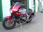
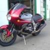
Looks good! Does it work as good as it looks? How about a side/profile pic? Please!
-
But this is a Guzzi forum, and unlike those bareback f.... we all have seat of pants to measure with. No need for bench testing in ten different ways. The only way to properly measure temperature of an object is to shield a thermometer from external influences (plastic adapter, duct tape) AND to ensure proper heat transfer (thermo-goo). Those who have TuneBoys, Powercommanders, whatnot, should use them. As Greg said, it is sufficient to "zero" the map after certain temperature point (again Cliff's OilT line gives a nice example). Others may resort to various tricks to fool ECU aiming for the same result - no influence of engine temp on the map after certain point. Trying to combine different tricks into a single one results in a setup one cannot control. Remember, the result of the EFI design is a compromise between two conflicting targets: - one to have engine running nice, which happens when it is running a bit rich - other to have engine consume as little fuel and to produce as little waste as possible, which happens when it is running as lean as possible. Ideally, when turning pot one should keep the work regime between these two "lines". Add air speed component to the setup, and you will be far more busy turning the pot than you would want to. I wrote earlier that emission tests are done at engine temps between 60-80°C. So one can safely zero the map at >80°C (with some risk even at >60°C) and still pass the test. If emission test is of no concern, one can go even lower. The map posted on MyECU page ignores everything >40°C. I understand you have possibility to change your map. Add goo, insulate adapter/sensor on the outside, towards the weather and zero any map adjustments over 40°C for the Engine/Oil temp. Take the bike for a spin, and report here. If it still sputters then your problem is most likely somewhere else (some other sensor, exhaust, whatnot...).
-
Everyone is a Philistine! Except Samson, of course...
-
luhbo posted his observations in this very topic about a decade ago. Try looking up his post.
-
Hook, line and sinker...
-
Yet he may get burned! Of course, not in such a dramatic way as Copernicus did. Still ratchet's fingers may itch (handling hot sensor). And yes, 40 will not do. It has to be 42.