Kiwi_Roy
-
Posts
2,343 -
Joined
-
Last visited
-
Days Won
61
Content Type
Profiles
Forums
Events
Gallery
Community Map
Everything posted by Kiwi_Roy
-
Guzz, The gauge was a no brainer for me, I am an Instrumentation Designer. It needs to have a few inches of rubber tubing at the ends where it connects to the throttle body so it doesn't drop off when hot.I will make another that can be used to check balance while the bike is in motion. Thanks for the grease info, so it's referring to overheating, I didn't understand that. I thought there might be some exotic seals or something. The PO was paranoid about lube materials, he gave me a crate of the special Italian oil mentioned in the owners manual. Cheers Roy
-
I used my new tool this evening, It worked like a charm. I did the TPS RH fully shut I found 102 mV so adjusted it to 150 This gave me a range 150 - 4890 mV. When I re-connected the linkage I got anywhere from 387 - 440 mV as I wrapped the throttle. This equates to about 1% of span so I wasn't too worried. I see several posts saying the mV should be about 500 with the linkage on. I adjusted the RH stop to give me ~500 mV. The LH body still on the stop When I attached the balance tool the difference was less than 2" of oil which is a very small error indeed. The bike was running about 900 RPM so I opened the left and right bypass screws until I got 1100 with both pressures balanced (about 1 turn on each) Then I ran the engine at about 3000 RPM, the pressure difference was about 4" so I tweaked the throttle linkage knob ever so slightly ( A few observations I figure that both throttle bodies should be sitting on the stop screws at idle because that's the most repeatable position 500 mV +/-10 mV. The 500 mV number is not really fixed like fully closed or WOT because it is effected by bypass screws and linkage backlash The main thing is to get a steady idle, I figure a repeatable mV should help there. Oil was a good choice of fluid for the manometer, during the test one of the tubes fell off due to the plastic softening with the heat, this resulted in some of the oil getting sucked into the other cylinder. I will find a short length of rubber tubing to modify the setup. Grease nipples are the cat's pajamas for connecting the tubes, just take the spring and ball out. I am confident that I have my throttle bodies well aligned no load. Next I will figure out how I can check it while riding with the motor under load. Once I have it to my satisfaction I will try out my Throttle Position mV offset rig. I cut the TPS wire near the ECU and inserted a M/F spade connector from here I will run a pair of wires to a mV source at the handlebars, I think +/- 100 mV (+/- 2% of span) should be about the right range Will keep you posted Roy
-
A similar thing happened to a buddy of mine on his KTM, accelerating around a curved on ramp and the back locked up. Of course he bit the pavement. to add insult to injury a cop came along and gave him a ticket for careless riding. Glad you're OK. please keep us updated, I have the same ride. Regards Roy
-
The manual says (picture of greasing the driveshaft) "To lubricate the cardan transissions use only saphonifying greasers with lithium of a grade 2 consistency, 265/295 penetration and with a dropping point of about 180* The lubricants must not contain additives with MOS2-33" Would someone like to explain that to me? My grease container says Heavy Duty Lithium and a few words of warning about not eating the stuff. It looks like pretty normal yellow grease to me but the manuals warning has me worried. Thanks in advance Roy
-
I finally got around to making a gauge for balancing the throttle bodies. 10 ft of clear plastic tubing and a lump of scrap metal. I used 10/30 oil as the fluid thinking it would be safer than water if it accidently got sucked into the engine. at first i thought it might be too viscous but when I tested it out seemed just right. Without making any adjustment I get about 8" at idle, falls away with some revs. I looked everywhere for barb fittings to screw into the body. Finally in a rare flash of brilliance i figured out 6mm grease nipples looked just right. I ground the back a little to let the spring and ball out, they work perfect. If I can just find some caps for them they will become a permanent fixture. Sorry about the sideways picture, just flip your monitor over LOL Cheers Roy
-
Yes, taking something of his bike for a reminder would be quite appropriate, How about those nice round nuts on the exhaust clamps, you could put them on your bike somewhere as a nice reminder of your friend, Every time you polished it. Cheers Roy
-
I downloaded the manuals V11 & Supplement. They all seem to come in 3 languages, rather than print all pages and throw away the ones I didn't need I took the file to work and opened the pdf with an edit program we have. I was able to get rid of nearly half the pages and print it out double sided. If anyone would like a copy of the abbreviated pdf send me an e-mail roy_matson at yahoo dot ca Regards Roy
-
That's really sad Peter, I'm sorry you lost your friend that way. I don't think I would even try and salvage parts off a bike like that, it should have been buried along with your friend. My V11 was in a similar accident, car turning in front but fortunately the owner came off with a few scrapes and i was able to purchase the bike and restore it. Broken headlight mainly. Again, my condolences on your loss Roy
-
That's great guys. I will have at it then. Will check out the manuals on the site you provided. Roy
-
That's great, I see you have changed the bars on your bike. This is something I need to do. Can you give me some details. Thanks Roy
-
I read the tech note about doing the valves. I have been putting this task off because I don't have new gaskets. Is it OK to put the old ones back? BTW, where do I get a decent manual for V11 Sport? Thanks Roy
-
Slightly off topic - when I replaced my relays I added an LED to the base of each one, It tells me if the relay is energized.
-
Thanks Tom, my bags are soft I will check out the spray next weekend. Will keep you posted. Regards Roy
-
Great idea, as an electrician I looked at the schematic and worried that the headight might fail with all those contacts in series. Using a separate relay for each filament should mean at least one will remain working. As a winter project I added an LED to the base of each relay wired to the N/O contact that way I can tell at a glance if one has failed to pick up Roy
-
Tried filing Aluminium, it soon clogs up the file. One of these surform files work great for removing a lot of metal in a short time. http://www0.epinions.com/Stanley_Surform_File_Shop_Tools Roy
-
I couldn't find a speedo shop locally, The shroud had a bad kink, must have got caught in the steering somehow. and very rusty otherwise I would have just replaced the inner with a kit from the local auto parts store. I put it on my Christmas wish list but unfortunately the one the supplied wouldn't fit. Apparently they have to get one from Italy. I'm not too impressed by the local dealer but buying on line usually works out more expensive with duty and broker fees. Thanks for the lube tips Roy
-
Thanks guys, that's just what I need
-
Hi, The speedo cable on my 02 V11 Sport is broken. I have ordered another one but the dealer expects it to be a month or more. Can someone tell me the speed in kmh for 1000 RPM in each gear so I can ride by tacho in the meantime. Thanks in advance Roy
-
Raz, I take it you used a resistor instead, about 120 Ohm I figure. You would need to use at least a 1/2 Watt to keep it from overheating. The incandescent lamps has one slight advantage over the resistor in that it's resistance is low when cold (~10 Ohms), this should provide more current to the thermistor so it heats faster and it goes up to about 150 Ohms when on. Having said that I might have used the resistor but I didn't have one to hand. How did you get on with the lampholders? I haven't tested mine with an empty tank yet. I doubt the bulb will ever burn out as it only turns on slowly but if it does it will be fail-safe as you say. Cheers Roy
-
I installed LEDs to replace the Incandescent lamps in my V11 Sport. I had a few problems which I will list below in the hopes that others will benefit. I ordered 74-R lamps from SuperBrightLEDs , 1 Blue, 2 Green, 3 Red $1.19ea. http://www.superbrightleds.com/cgi-bin/sto...mini-wedge.html 1) First of all I tried a direct replacement without success. The bases look similar but on close examination the LED contact wire is wrapped around the end of the base and bent back so it makes contact on both sides (see print) shorting out the lampholder. I tried clipping one side off the wire, this works but not well as it's a little tricky getting it into the base. Since the LEDs are long lasting I decided to remove the contacts and solder the lamps in place. The rubber base comes out quite easy with a bit of tugging and the new lamps fit snugly. 2) Because the wires have oxidized over the years I had dificulty getting a good solder joint so I clipped the brass contact off leaving the crimp part which is much easier to solder too. Once the wires were connected the lamp slipped back into the rubber base. 3) Unlike incandescent lamps LEDs are uni directional (diode) so you need to make sure they are connected up with the right polarity by turning on the ignition and touching the lamp to the wires. Current in the flasher circuit indicator lamp flows in both directions from the active side to the non active side so it needs some additional components. I added a bridge rectifier from Radio Shack. A couple of diodes will also work if the negative side of the lamp is connected to the chassis (see print). 4) My V11 Sport has a thermistor type low fuel sensor, this draws about 20 mA with the tank full. The heat this produces is carried away by the fuel. When the fuel is low the thermistor is no longer kept cool so it heats up, the resistance drops, the current goes up some more until it draws enough current to light the incandescent lamp. Unfortunately the 20 mA the lamp thermistor draws turns on the LED as it only requires 10 mA for full brightness. The solution is to add some additional load in parallel with the LED. I could have used fixed resistors but one of the old lamps in parallel does a better job. If your bike has one of the reed type level switches the additional load will not be required. In hind sight I should have ordered 6 new lampholders from SuperBright to replace the Guzzi ones. These would have saved me some work and they wouldn't short out like the Guzzi originals. I don't see a suitable holder on their website but I'm sure they have one. (the T10S-SP is too large) The colour of new LEDs should match the colour of the lenz otherwise they will look dull. If you have trouble pulling the old glass lamps, pull the rubber base out or a slide piece of plastic tubing over the lamp so that long nose pliers will get a better grip. Although it took me about 3 hours I am very pleased with the results. The LEDs are more visible in bright sunlight. While I was at it I added an LEDs to the N/O contact of each relay, but that's another story. Have Fun Roy Guzzi_Lamps.pdf
-

it's spitting back alot and wont run well
Kiwi_Roy replied to motoguzzimick's topic in Technical Topics
Take a look at my post "Throttle Position Offset", you might find it usefull Roy -
Hi, A set of Tekno saddlebags came with my V11 Sport, These have faded in the sun to sort of light purple colour. Does anyone know how to restore these to Black. I cant seem to find who makes these, does anyone know manufacturer, web site etc. Thanks in advance Roy
-
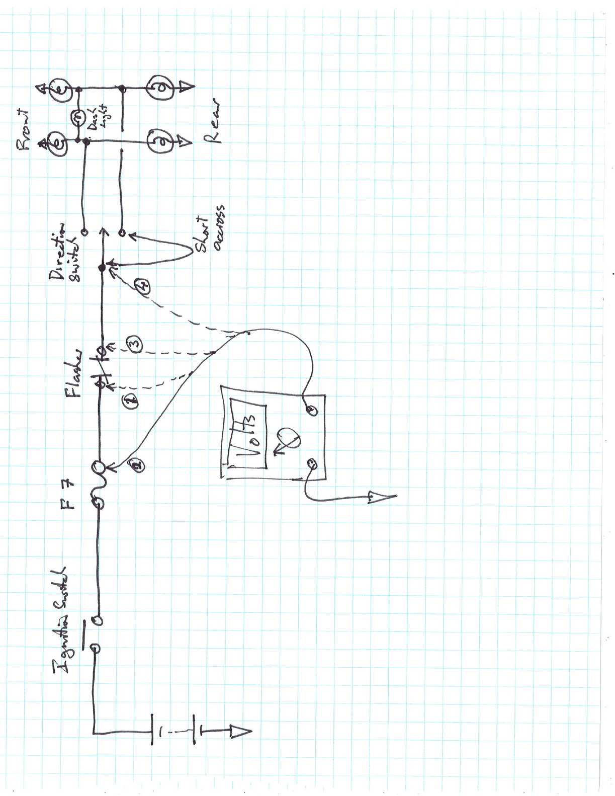
A quick check you can do with a multimeter (or 12V lamp) With the key on, unplug the flasher, is there 12 V on one terminal If No check Fuse F7 If Yes and none of your 4 flashers light up no matter where the switch is the chances are its in the switch. Its quite easy to pull the switch apart but be carefull not to loose any of the small parts. Once you have it apart turn on the key and short between the center terminal and either of the outside terminals with the key on if the flashers go the fault is in the switch. You can also check for voltage on the center terminal. I doubt it.s in the wiring from switch to flasher lamps, it would be quite unusual for both sides to go at the same time. Keep us posted. Roy
-
Thats great news. To prevent future problems apply petroleum jelly (vaseline) to the terminals. This keeps the Oxygen from the metal so that Lead Oxide cannot form. Lead Oxide is a hard light grey insulating layer that mostly forms on the negative terminal. I learned this trick as an apprentice working on large traction batteries. Roy
-
Yes, you could easily measure it but that makes it more complex. The idea was to set the pot for best performance then square it all away later e.g. measure the mV with the throttle closed, remove the circuit and set the sensor to give the same mV I haven't tried it and probably won't get a chance for a while (next riding season) Regards Roy