docc
-
Posts
20,491 -
Joined
-
Last visited
-
Days Won
1,188
Content Type
Profiles
Forums
Events
Gallery
Community Map
Everything posted by docc
-
There are some replacement mounts available for the coil mounts from Touratech. When you replaced the timing sensor, you are certain it seated fully and everything got plugged back up? This doesn't sound like TPS at this point. The two nipples on the bottom of the tank each get a small hose that drops out behind the gearbox (one for tank vent sometimes has a small one-way valve in line, and the other for tank over flow). So, what does the bike actually do? crank over, fuel pump primes, starts and stalls?
-
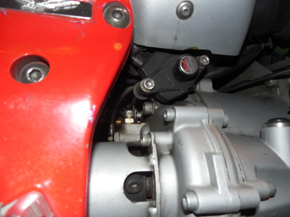
All about right except docc didn't solve the mystery. Kiwi-Roy to the rescue, and gstallons who also saw this for a bad connection. Makes perfect sense (now) that the starting was seeking a new ground path that couldn't take the juice. The main ground strap is a little hard to see, but look under the seat release at the back right of the gearbox and the terminal should be visible:

-
They look to the best of what Moto Guzzi is building. A very nice choice and really good all around motorcycle! Excellent choice!
-
I could be asking the wrong questions. But, there's no doubt that melted black wire is trouble. And we know it went to the negative side of the battery. So, where did it go forward from there? Had to come from somewhere . . . The other end of the wire?
-
The good thing about continuity testing is you're using 1.5 volts from the Ohm meter and it leaves very little smoke to get out of the wires. The question about your melted black wire is: where did it come from on the front of the bike? Is it the regulator ground?
-
C'Zak: Just to be sure: when you traced the bad wire to the battery, it went to the negative side for sure? The picture looks like a black wire form the factory harness (not an add-on from the PO). Can you confirm this? If so, my schematic seems to only show black ground wires from the headlamp and the regulator. And one big, short one to the back of the gearbox. Some continuity testing using an ohm meter with the key off might be a good idea to find what is connected where. Most of us would not use a black wire to power positive to a vehicle device, but . . . ?
-
But that ground . . . I'm thinking of it as coming back to the battery. But from where? The regulator? Maybe the headlight? That will be where the short likely began. And what about The Mystery Ground? What was that wired to?
-
So, the ground actually was from the regulator? It's just that you can't actually short a ground to the frame. So, if there wasn't a hot wire melted into it, I would think the regulator played up and shorted itself through the ground wire. 1) Is there a separate ground to the regulator case? 2) What does the green 30 amp fuse and its connections look like? 3) You could mention the two lovelies at the bank to the wife and probably get of of dinner plans.
-
c-zak: post your voltages across the terminals: key on, idle, 2500 rpm . . .
-
Grounding is known to be rather lacking in this design so, yes, there are grounds running the length of the wiring harness back to the terminal stack on the battery. The black one may be from the regulator. The white is power to the Run Switch from the middle relay and only energized when in neutral. Your trace will tell for certain. No doubt you're onto the culprit!
-
I didn't do any readings above 4000. With no accessory load, the 14.2 volts is steady from 2500 to 4000. Better not check it tonight - she really howls down here in the basement on the lift as the revs climb!
-
Key on : 12.74; idle: 12.56; 2500 rpm: 14.2. Jacket and gloves on: idle: 12.25; 2500 rpm: 12.65; 4000 rpm: 13.0 77 watt jacket only at 4000 rpm: 13.5.
-
Hubert , " P / A / S ?"
-
Whew! Four hundred bucks. I guess that's not so bad if you're replacing a failed stock item. I wonder if the regulator is up to the extra current? It doesn't even seem happy with what it gets now. BTW: "hl relays" would be headlight relays. I suppose if they have heavier gauge wiring and heavy duty relay contacts, the current draw might be reduced somewhat, but the bulb is still going to get its 55 or 60 watts. Seems like we came up with a running demand of about 170 watts for the V11. I forget the methodology there, and it could be dubious. No doubt, adequate output does come on more like 4,000 rpm if every thing is working well (regulator grounding, healthy 30 amp fuse, quality relays and good connections). Attempting to run Gerbings heated gloves and jacket (22 + 77 = 99 watts) could have been the end of my last regulator . . .
-
Both the front and rear axle nuts on my Sport are 27mm across and deep enough to take the cover off.
-
Let's look at your relays and their connections . . .
-
As if these bikes weren't dicey enough coming out of Mandello, now we're three (or more ) owners on and have dangling wires with sheet metal screws? How to undo what has been done? And begin again . . . Factory had several loop terminals on each of the battery posts. Not that this was a good idea . . .
-
There is a great thread (back there, somewhere) where one member did some extensive testing on gasket deformation versus the tightening procedure. I think it was Ryland3210 and the conclusions were interesting. From what I recall, the best result was obtained (using a "quality" filter) by tightening one-and-one-eighth turn after gasket contact. It is tighter than I would ordinarily turn a filter up "by feel" but has stood the test of time. +1 here on the WIX. That and not letting your oil level fall even a half liter low are good bearing medicine!
-
It takes a Special Kind of Guy to get the smoke back in the wires with chicks watching . . .
-
Make sure there is nothing hanging down on the left side fouling the throttle cable. 27 mm nuts are pretty easy to come by on early Sports: one on the front axle, one on the rear . . .
-
Somehow your throttle plates have gotten too far open. I would return to the right TB, release the linkage, release the high idle cam (just loosening the cable is not enough), and THEN make sure the idle screw makes no contact. Set the TPS for 150 mV, re-attach the linkage and turn the left hand idle screw until the TPS gives around 525 mV. Air screws should be happy at 1/2 to 1 full turn out, but not idle well or at all closed.
-
What is the proper libation to drink out of a "Guzzi cup?" Coffee? Lambic? Chicken soup?
-
I had said to set the closed throttle body TPS at 165 mV, but it truly is 150 as Kiwi_Roy had said. Where did yours end up and what is your TPS mV at idle?
-
Post back what you find! Just looking, I'm not entirely sure the driveline paint and the wheel paint is the same (?)
-
So, there! I asked for it, I know.