

Kiwi_Roy
-
Posts
2,343 -
Joined
-
Last visited
-
Days Won
61
Content Type
Profiles
Forums
Events
Gallery
Community Map
Posts posted by Kiwi_Roy
-
-
Some of the Electrosports are a direct replacement so they suffer from the same flakey Voltage reference.
Which model did you buy?
-
I find the easiest way to gap the sensor is to stick something like a glob of JB Weld on the tip, bolt it in place, wait for the JBW to set up then remove it again and measure the blob with a pair of callipers.
-
Are you also posting on Wild Guzzi that would improve your chances, all the Guzzis back then used the same sensor
If not a member on there somehow send your cell No so we can link you up.
-
 3
3
-
-
23 minutes ago, jetboy said:
Fuel pump turns on and pumps fuel. Used that to clean the lines of the possibly bad fuel!
Sadly i am sending this from the side of the road. Ran beautifully for about 2 miles then just stopped. And back to doing the weird rev cycle. Still waiting on pick up. Should be here in about 30 min
So the fuel pump is running but just for a couple of seconds?
Is it still running while cranking over, if not it's probably the Phase sensor.
The phase sensor turns on the injection relay through the ECU, the injection relay turns on the pump and the ignition coils, if the Phase sensor dies you lose the injection relay, pump, spark & injectors. You could make sure no-ones added extra spacers to the sensor, sometimes that gets done in an attempt to make it oil tight. The gap should be 0.6 - 1.2mm.
Probably your best bet to find another sensor is to borrow one from a local Guzzi owner.
-
4
-
 1
1
-
-
As Tomchi said, here's the schematic, the sensor has a short cable plugged in under the tank somewhere, measure between 1 & 2.
Note also how the petcock fuse is right on the critical path battery to ECU relay, if you hot wire to fuse 8 it will also energize the ECU relay, the ECU will energize the injection relay.
Actually that's a good point, does the fuel pump run when you turn the key On, if not it's something missing in the main interlock circuit. The pump will still run even if the Phase sensor has failed but only for a couple of seconds, if the pumps not running for the initial 2 seconds chinches are the Phase sensor is OK. (its a while since I looked at an old guzzi wiring LOL)
When you turn the key On the pump runs independent of the sensor but only for a couple of seconds. When you crank the motor the sensor lets the ECU know and it turns the pump back On
Actually for the starter to work, ignition switch, Sidestand relay and kill switch all have to be closed, that feeds the Start button.
-
2
-
 1
1
-
-
It might well be the phase sensor others have suggested but it could be just a simple electrical fault. I would hot wire from the battery to the ECU, that will tell you one way or the other.
The phase sensor is a very simple device, just a coil wound over a small magnet but it's absolutely vital, a good idea to carry one on a trip because there isn't work around that I know of.
Sorry I don't seem to be able to post a link here but basically you need to be able to liven up fuse 8, the petcock fuse, that will back feed the ECU relay and so turn on the ECU. Be warned this will bypass the ignition switch, side stand switch and kill switch but that beats being stuck on the road.
An alternative is reading the Voltage at fuse 8 with the key On, it should be alive, if not it's one of the 3 switches I listed above.
I had a light on fuse 8, Docc named it the Go Winkie light.
-
2
-
-
Those brackets are super strong, i used to pick up the rear of the bike by the brackets.
-
It doesn't come on a stick like the VII ones but I'm fairly sure its value is the same, it would certainly work with an in tank fuel pump. You could adapt the V7 one by carving open the stick to access the connections. I would try to avoid having to re-make the tank seal.
-
1
-
-
The sensor is a thermistor, no capacitance at all just resistance that changes with temperature, yours read 1.4k because it was reasonably warm then you dipped it in fuel and cooled it down.
I just went through this again with a V7 owner, he took the regular speedo off snd wanted to use a 12 Volt LED in its place.
He tried using the LED directly with his sensor but of course found it was always lit.
I tried to talk him into using an incandescent like the VIIs use but he wasn't having it
Measuring the sensor on my V7 the thermistor is ~1,800 Ohms when cold (it will vary slightly depending on your fuel temperature) When the fuel drops below the sensor the V7 sensor starts to warm slowly until it's only around 90 Ohms.
You have to be really careful not to supply too much current as the sensor will just keep getting hotter and hotter until it fuses in a puff of smoke, the small lamp that the VII comes with is nicely balanced for the sensor, as the current goes up it lights and the current falls back. The V7 dash does a similar thing electronically, it limits the current to 75 milliamps.
I worked out that 150 Ohms was a good value to use in series with the sensor, it will pass enough current to warm it up but not enough to fuse it, the 12 Volt LED is wired in parallel with the resistor, it doesn't draw anything when the sensor is cold but is reasonably bright when the sensor warms up
-
2
-
1
-
-
4 hours ago, Steve S said:
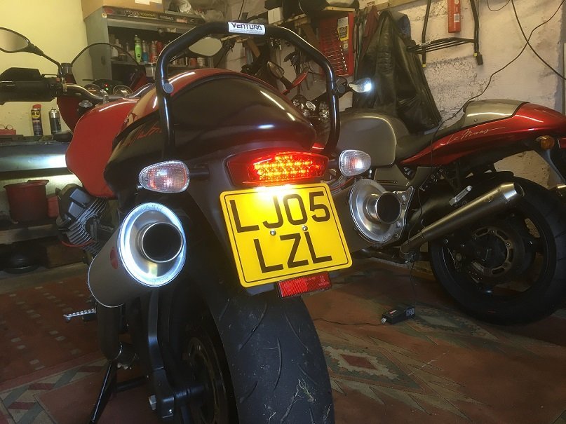
I did this as I had a spare mudguard so got rid of the number plate lamp, the LED lamp has one built in
Steve,
Do you have the part No of that lamp, I bought one for my old Eldorado but couldn't find it again when it came time to do the griso.
I ended up adding a pair of white LEDs
-
As for running LEDs in the indicators you will need a different flasher unit, the OEM flasher operated on lamp current. The current would heat up a bi-metal strip which would bend so the contact sprung open then cool down to close and repeat the process. The only way to make this flasher work with LEDs is by adding huge resistors to take the place of the incandescent lamp load, this is too crude.
With LEDs you need a flasher unit that will open and close at zero current, these flashers normally have a third wire connected to chassis.
Then you need to re-wire the idiot light, it came from the factory connected between Left and Right indicators the current drawn was insignificant compared to the incandescent lamps in the indicators, about 100 mA but with LEDs that tiny current is many times what the LEDs draw.
All you need to do is wire a small diode from each side pointing at the idiot lamp with the other side of the lamp to chassis. The diodes prevent the lamp signal getting from Left to Right indicators, even if you change the idiot light for an LED you will need the diodes. This change takes place inside the dash, no additional wires except the new ground for the lamp.
If you decide to change out the incandescents in the dash for LEDs don't even think about using the original lamp holders.
BTW, if any of you also have a CARC Guzzi you do need to add a shunt resistor (just a tiny 1K 1/4 Watt) to some LEDs to keep the lamp alarm happy and stop the lamps glowing with the key off.
I tried to add a sketch file but it's even too large at only 200 dpi
-
2
-
1
-
-
I like Footgoose's tail tidy, I made something similar for my Griso using the original tail-light but added some white LEDs to illuminate the plate.
I just made mine of aluminium, much easier to work than stainless and holds a high polish.
I think you need a rear hugger before adding the tail-tidy.
-
One cause of slow cranking is a bad ground connection. If the ground is not making good contact the return current from the starter finds its way back to the battery via the small ground wire from the Voltage regulator. Too much of this and the wire becomes red hot melting through and shorting to other wires in the loom. Make sure the main ground is connected to a gearbox bolt and not just the seat release lock.
The battery terminals should be cleaned and protected with Vaseline.
Measure the Voltage across the starter terminals while cranking (should be at least 10V)
Battery Positive to Starter Positive (the battery terminal not the wire lug) (<1V)
Battery Negative to chassis (as above) (<0.5V)
Battery Positive to Negative while cranking (should be at least 10V)
Of course the LiPo batteries are known for weak output when cold.
-
1
-
-
I used Helicoils on my VII Sport tappet covers, most of the holes are not blind,
They make a job that's better than original.
-
2
-
-
I've forgotten but isn't the steering stem on the V7 hollow?
Just use a piece of rubber hose with a bolt to squeeze it from the end to expand into the stem. No need to make it round if its hex at the moment.
-
On 11/2/2020 at 10:46 AM, docc said:
The regulator does ground back to the battery through the loom to one of the ring terminals. Cleaning and treating the rings and terminals is a good idea, as is adding a ground from the regulator case to the engine or timing cover.
Also, it occurs to me to suggest conditioning the battery with an approved charger and method (assuming it is an Odyssey PC545) rather than expecting our charging system to bring a needy battery up though that pitiful little fuse.
The problem is this wire has too much resistance, it has to carry the same 30+ Amps peak current as the Red positive wire from the battery back through the regulator to the other end of the stator winding.
The Red positive wire can afford a few Volts drop, the Voltage regulator takes care of that but the Black Negative cannot afford any Voltage drop, half a Volt there is taken directly from the battery Voltage Reference.
Remember the voltage regulator is hanging on a bracket that's not even grounded properly, just accidentally grounded where the paint scrubbed off. A short wire from the regulator case to a timing cover screw is like a massive cable through the mass of the engine/gearbox to the fat battery ground.
It's only the earlier Ducati Energia regulators that need grounding, the later bikes have a direct connected regulator as shown, item (22)
-
4
-
-
9 hours ago, docc said:
Nicely put, Kiwi_Roy!
So (on the early wiring), blowing Fuse5 during a start attempt could be connections to the Starter Solenoid or faulty starter (like the common internal loose magnets)?
If it blows turning the key on (Start Relay normally closed), the fault is in the Headlight Relay circuit?
That sounds right the headlight relay would close but I don't see how loose magnets would blow a fuse. A loose main battery connection could cause the fuse to blow, the heavy current coil is turned On until the contact closes feeding 12 Volts to the motor armature, I tested that by loosening the positive feed to the solenoid, the fuse blew in less than a second.
-
1
-
-
From my notes, there are two coils in the Valeo solenoid (the old Bosch and the new Chinese starters all have 2 coils as well)
One is 1.05 Ohms from the spade connector to chassis by Ohms law that will draw 12/1.05 = 11.4 Amps, this coil is powered up as long as the bike is cranking over. (I call this the Holding Coil, it can never close the solenoid just strong enough to hold it in place)
The other coil is only 0.25 Ohms and goes from the spade connector to downstream of the main contact and across the armature. (I call this the Grunt Coil, it does most of the hard work if its wired right that is) The Grunt coil is turned off once the solenoid is engaged.
The armature is so close to zero ohms you can ignore that so by Ohms law 12/0.25 = 48 Amps, add the 11.4 and you have 59.4 Amps, in reality you get about 40 Amps. On the later bikes you get Startus Interuptus, the wiring is not up to it so the Voltage drops and the relay just clicks.
Solenoid Magnetic Strength: The two coils both have about 300 turns, the magnetic strength is Amps x Turns = 3,420 AT for the first coil, 14,400 AT for the second coil (4 x as strong if its wired right)
BTW if you try to measure the currents you cannot do it with a multimeter, the heavy current only lasts for about 50 milliseconds, too quick for a digital multimeter, there are ways of doing it if anyones interested.
I have helped dozens of owners with Startus Interuptus, some other models suffer worse e.g. the CARC models that the wire from the relay to the solenoid is really tiny, it would be ok if the current was only ~10 Amps but its a real choke point for 40 Amps, my 07 Griso operated 3 x as fast just by increasing the wire to a No 18. Of course on the later 8 Valve bikes the wiring is even worse, they choked the current through the switch again.
I wrote a letter to Piaggio about the problem, they sent me an acknowledgement but I suspect they filed it in the trash.
-
1
-
3
-
-
12 hours ago, Tom in Virginia said:
Have same starting issue on 2002 LM, like new condition with 3000 miles now. This bike consistently blows fuse #5, thereby loosing lights, tach, etc. Surely a factory "installed" problem. lol. However, on the 2003 LM never have had any problems in 25K miles. Starts every time and never has burned any fuses.
Fuse No 5 on the earlier VII should be a 20 Amp, not a 15. These earlier bikes are better wired in some ways, Fuse 5 is direct from the battery and feeds the Start relay, you should never have a problem with it failing to crank (provided it hasn't blown the fuse). The later bikes late 2003/2004 have the start relay fed from a switched fuse so they suffer from "Startus Interuptus" like many other models, how do I know this, because my 2001 was wired direct. I couldn't understand what SI was about until one day I discovered there are two coils in the solenoid, the solenoid has an inrush current around 40 Amps (too much for a 15 Amp fuse).
Trace the wiring to and from Fuse 5
It comes straight from the battery, goes to the Start relay through the normally closed contact to the headlight relay.
Compare it to a later model.
Here the start relay is fed from fuse 4 via the ignition switch, a 15 Amp fuse will probably never blow because it has half a mile of tiny wire to limit the current and the ability of the solenoid to engage the starter properly. You cannot simply feed the start relay direct or it will turn the headlight on, there's several ways around that.
-
3
-
-
You need to install a Go-Winkie light, it will tell you you have a fault and as you go through the sensors it will tell you when you touch the bad connection.
Hot is a broad term, too hot to touch?
-
1
-
-
It's probably in this thread somewhere, the reason for the 30 Amp fuse melting that is.
The cause as I see it is too much resistance in the clips holding the fuse, resistance causes heat at a current squared relationship and don't forget the current is pulsing, its not a steady DC but a pulsing DC, the peak is much higher than the average.
So saying my VII Sport welded a fuse into the holder but I was able to break it free and clean the socket up again. It never gave me another problem but I eventually replaced the regulator with a direct connect type.
Don't re-use a fuse that has overheated toss it and replace with a new one.
-
3
-
-
30 minutes ago, Tinus89 said:
Awesome...
Anyone who can shine a light on which part this is and it's function? I can't locate it on the wiring diagram...
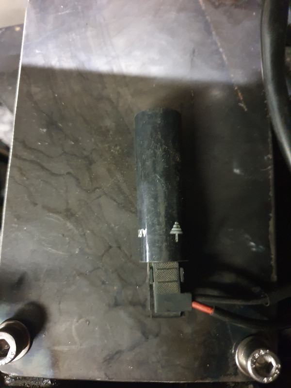
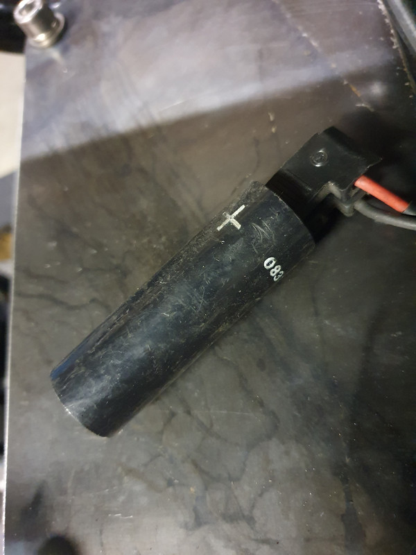
Its hard to know I can't judge the size, is it possibly the coil for an electric petcock
http://www.thisoldtractor.com/guzzi007/schematics/1999_V11_sport.gif item 32
Does the red wire come from Fuse 8?
Owners sometimes remove the electric valve and replace with a manual petcock.
What is the complete part No we can see just 083
-
Actually the regulator is set for ~ 13.8 Volts, by the time you get some Voltage drop through the headlight relay the battery ends up a little higher say 14.3.
If the regulator reference was connected directly to the battery it wouldn't go over 13.8.
How do you do that?
Either use a dedicated relay or look for another relay that has less load on it. Adding after-market headlight relays will do that also
[url=https://ibb.co/4sWhKc1][img]https://i.ibb.co/bH1cQxb/Ducati-Energia-Schematic-w-Notes.jpg[/img][/url]
-
It really doesn't matter which you run to, the battery positive or the live terminal on the starter solenoid, the battery post usually has too many on already and it depends on where you mount the relay, close to the battery or close to the starter
Not the one that connects to the starter motor, the one that connects to the battery.
Here are the drawing files, but no perving at Carl's girlfriend mind you. Scroll down without looking!
http://www.thisoldtractor.com/guzzi007/sportissimo.html
-
1
-
1
-
1
-
Headlight Grounding
in Technical Topics
Posted
Solid wire like that has no place on a motorcycle and please use lugs
On a high milage bike you may find the wires are starting to break around the headstock, if you can separator them reef on each wire one at a time, the broken ones will stretch and break.
You can run a short wire from the headlight and ground it to the frame or an engine bolt to bypass the long black wire back to the battery, dont pass any current through the steering bearings.