

Kiwi_Roy
-
Posts
2,343 -
Joined
-
Last visited
-
Days Won
61
Content Type
Profiles
Forums
Events
Gallery
Community Map
Posts posted by Kiwi_Roy
-
-
I just came back from 6 weeks holiday, (central Nth island), unfortunately the computer I had wouldn't access this site.
If you are still having a problem we should be able to sort it out fairly quickly.
You should have been able to get the switch apart, as far as I know they are all the same, the root cause is probably dried out lube inside
-
 1
1
-
-
On 3/3/2022 at 8:34 PM, Lucky Phil said:
The ecu draws unswitched or un relayed current from the battery so the battery drains no matter what you do.
Ciao
The ECU drain is only microamps, the 525 regulator shouldn't draw anything from the OEM wiring because it's connected downstream of the headlight relay. The black wire acts as a Voltage reference but it also powers up the electronics.
-
 1
1
-
-
7 hours ago, bbolesaz said:
I installed the ESR515. Here in the valley of the sunstroke, it drains the battery in a few weeks. I'm planning to install a new relay switched with the key to break the red line when shut down.
A good idea
But actually doesn't the 515 connect to the headlight circuit just as the original Ducati energy did?
The headlight circuit already has the relay, I could put my VII Sport away at the end of summer and start right up again in the spring, no battery tender required.
-
On 2/18/2022 at 6:41 AM, dbarb3 said:
here is the little bit know I know
Changed out relay 2 no change
Tach not working, headlight on
Charging light not lit Of course it doesn't work when you need it to, it needs 12 Volts from the headlight relay to turn it on.
Battery engine off 12.15 Engine running 11.5
Obviously not charging, check wiring at alternator next??
From page 1
I couldn't figure out why the Tach had stopped but the headlight was still on (the tach is fed from the headlight relay), then I remembered perhaps you have after market headlight relays which bypass the OEM headlight relay.
-
1
-
-
This is the one I used, the ESR510, it completely eliminates the flakey Voltage reference. One thing to be aware of though it does draw a tiny current from the battery that will drain it down over the winter. You can eliminate this current by pulling the fuse over winter but you'd better remember to replace it in the spring, don't ask me how I know.
Electrosport say,"Because many older Ducati's suffer from poor wire connections in the wiring harness we designed the ESR510 to have output wires that are connected directly to the battery terminals. The lead wires also have a 20A fuse inline for security"
They also have a plug and pray model the ESR515 but I couldn't wait to get rid of the unreliable Voltage reference down from the headlight relay.
-
2
-
1
-
-
How about some BA9s from Superbright.
Actually go through the whole bike and get LED replacements and make it worth the postage.
https://www.superbrightleds.com/moreinfo/miniature-and-subminiature-bulbs/194-led-bulb-1-led-miniature-wedge-retrofit-car/197/ These are great for the dash buy all the colours to match the lens, the nice thing about the 194 is they are an AC lamp so you don't have to worry about polarity, they have a shoulder that fits into the white holder and you can solder the wires direct to the lamp because they should never need replacing. I use the 90 degree ones.
For the direction indicators perhaps
With an LED flasher- you can buy 2 pin ones but i'm more confident in the 3 pin variety with a ground conection.
Head light bulbs are a bit of a crap shoot. I think they will be an H4, I currently run a fan type in my V7, I opened up a hole in the rear of the bucket to let it stick out, flush actually. You will find better deals by just googling.
-
1
-
3
-
-
20 hours ago, dbarb3 said:
Tach not working, headlight on
Charging light not lit
Battery engine off 12.15 Engine running 11.5
Obviously not charging, check wiring at alternator next??
If you don't have a Voltage reference to the regulator the regulator cannot turn the charging light ON and neither can it turn on the SCRs to charge the battery, Check the black wire of the black / white pair, should be 12 Volts with the ignition ON
The Black wire plugs into the female of the M/FM pair, its Red/Black on the loom side, connects to the headlight circuit downstream of the headlight relay, its actually soldered to the headlight feed under the tank.
The Male pin on the loom side goes to the charge light, the light will turn on if you ground that pin. The light gets +12 Volts from the same wire that powers up the Tachometer.
There are quite a few variations on the wiring but this is always the case, if you are looking at the M/FM connector on the loom side the Female should show the battery Voltage when the key is On (without this the regulator cannot work) the Male should also show the battery Voltage but if you touch it to chassis the charge light will turn On.
Make sure the regulator case is well grounded to the engine, don't rely on the black wire that goes all the way back to the battery, its just a token ground.
-
1
-
2
-
-
If the Tach stops working check to see if the headlight's off as well, the regulator gets its reference from the headlight feed after the headlight relay.
If the reference is missing the regulator never turns on.
-
2
-
1
-
-
I used the drive to spin a magnet activated reed switch for a pulse input Speedhut.
-
2
-
-
12 hours ago, 4corsa said:
Have been meaning to post this for a couple weeks, and seems like a good follow-up to Kiwi_Roy's post above. I made the ground from my new ElectroSport unit as shown. I believe the wire is 14 ga., and I did sand off the paint at the connection point.
Please note this photo is taken from below looking up - the wires aren't really visible from standing position.
Sent from my Pixel 4a using Tapatalk
You can see from the picture the bolt and spring clip do a very poor job of grounding the regulator, there's up to 30 Amps flowing between the painted metal bracket and the case, also I believe that bracket is bolted to the chassis with painted to painted surface, your beefy jumper wire at least has a fighting chance. I hope you used some form of corrosion inhibitor.
I have in the past suggested that an aluminium strap could be used instead of copper wire cutting down on the number of different materials.
I'm guessing you used an ESR515 which has no ground wire.
-
1
-
-
Another word against the small black wire guzzi provide,
Some owners have experienced a poor connection on the main battery ground, in this case when you try to start the starter current tries to get back to the battery through the regulator ground turning it red hot which causes it to melt the insulation off other wires in the loom, I used to have a picture of that mess.
On my 2001 the regulator was fitted to the horn bracket, nothing had been done to remove the paint from where the bracket contacted the chassis, A short wire from the regulator case to a timing cover screw takes care of all that..The other problem with the Ducti Energia regulator is it takes it's Voltage reference from the headlight circuit downstream of the headlight relay, that point can be anywhere from 0,6 to 1 Volt lower than the actual battery Voltage. Battery charge current vs Charging Voltage is some sort of exponential relationship so if you drop too much at the reference point you wind up with too much charge current and cook the regulator.
IMHO you are much better to have a modern direct connect regulator even with its tiny leakage current.
The modern V7s use a Chinese Shindengen regulator, I would use one of those before I bought another Ducati Energia.
Look at Carl Allisons schematics on Greg Benders site, you will see the difference there.
-
2
-
-
He sent ne a set as well, What would we do without Pete?
-
On 11/16/2021 at 5:30 PM, p6x said:
@docc I read that thread, and all the others that treated of that subject. And there are many throughout the years.
From K-Boy, I got that the starter load is carried through the switch via these flimsy poles on a plastic tab.
However, on the LeMans, it is not a 15 minutes job. There is no easy access to the two screws that hold the contactor switch.
Today, the starter cranked right on point.
I am trying to make sense of what made the jump start successfully the other day. If the poles were not properly in line, the starter should not have cranked. Unless of course, the jump added enough CCA that the poor alignment carried enough Amps.
No, the starter load is not carried through the ignition switch, just the solenoid load is. the starter motor itself will draw 150 - 170 Amps
I don't believe the switch is rated at any more than about 10 Amps, I cannot find the specs.
The solenoid has a massive job to do, it has to slide the gear all the way across to engage with the ring gear, I think it takes something like 30 Amps minimum to do that, but the solenoid is designed to pull 50 Amps so why not use all that power.
Power = Current squared x resistance, the heavy current coil is 0.25 ohms
At 30 Amps the power draw is 30 x 30 x 0.25 = 225 Watts
At 50 Amps the power draw is 50 x 50 x 0.25 = 625 Watts
Which do you think might work better?
This high current to the solenoid only flows for a fraction of a second, as soon as it starts to crank the heavy coil is effectively switched out and the light coil just draws ~ 10 Amps
I often see an owner say the bike cranks ok in warm weather but plays up when its cold, there's a very simple explanation for that. The ignition switch has sliding contacts and sliding contacts need to be lubricates or they will quickly wear away. When it is cold the lube becomes much stiffer than normal so it tends to take tension off the contact point therefore the resistance increases to a point that there is insufficient current flowing to get the solenoid moving 1/2 an Ohm is too much. Petroleum jelly aka Vaseline has been used for over 100 years to lubricate sliding contacts. As it ages the jelly loses some of the more volatile components this also makes it stiffer.
I think if you were to clean and replace the lube in the switch every 4 or 5 years it would probably keep working ok but I recommend bypassing the switch altogether and give the solenoid the current it was designed to operate on i.e. 50 Amps. The easiest way to do this IMHO is to add another relay next to the solenoid using the original trigger wire to feed the new relays coil
If you look at the schematic for a 1999 VII Sport you can see that the start relay on that model doesn't get its power through the ignition switch, instead it gets it from the battery through a fuse the one I had never hesitated to crank all the time I owned it. Another bike that got it right was the early CARC bikes, they also have a direct feed where later ones hav extra relays and still suffer.
-
2
-
2
-
-
Yesterday, October 6th 2021, the starter motor did not crank immediately upon pushing the switch. The Neutral and low oil pressure lights dimmed, so the current was drawn, but the starter only kicked in after about one second.
This morning, the same situation happened, but it blew the 15 amps mains fuse.
The battery is fine.
I changed the fuse, and started the bike. Same issue without blowing the fuse. The starter motor did not crank right at the button push. The light intensity showed the current was drawn but the motor did not turn run away. It took about one second.
Could be a sticky starter motor, or a going bad relay.
Unfortunately, the OMRON G8HE-1C7T-R-DC12 DC12V does not seem to be available from a trusted seller. I found some on Amazon or eBay, but the sellers have warnings from "fakeguard".
Anybody has any available for purchase?
LMK
Please excuse me if someone covered this already in the 7 pages I didn't read closely
p6x, reading your original post it sounds like classic Startus Interruptus, not enough current getting to the starter solenoid. Possibly as the result of a dirty ignition switch, it could also be a relay or relay base resistance but my monies on the ignition switch. Pull it apart and wipe out the old grease replace with fresh Vaseline.
The solenoid needs an inrush of about 30 Amps to goad it into motion so just a tiny amount of resistance and it falls in the 20 - 25 Amp range where it will cause the 15 Amp fuse to blow.
The starter solenoid is designed to draw 50 Amps, its amazing how well it works when it's wired accordingly.
-
1
-
1
-
-
If you find the spade connector on the solenoid loose thats a sure sign it has been overheating due to resistance. The metal has annealed loosing tension. Replace the spade connector and don't forget to apply some Vaseline to the wire before you crimp it on.
On many Guzzi's this wire from the relay to the solenoid is too small, you can easily lose a Volt and 10 Amps at the solenoid right there, a 16 gauge or metric equivalent is about right.
On my 06 Griso I up-sized this wire one size, the time to engage the starter dropped from 50 milliseconds down to 15
-
1
-
1
-
-
19 hours ago, p6x said:
You only hear the relay underneath the seat. Absolutely no sound from the starter. This is why I suspected the Solenoid.
The battery terminals are shiny. No sulfate, nothing that could create a resistance.
I will get to the bottom of this issue next week.
Its probably not the solenoid, the wiring is not delivering enough current. You only hear the relay under the seat because the solenoid is not getting enough current to start it moving. (I should add the solenoid plunger could be stuck if its gummed up with grease, I just use a couple of drops of 3 in 1)
Do the simple test of hot wiring the solenoid from the battery, if it's easier take the starter relay out and touch a wire from the 87 contact to the battery Positive. You don't need the key On to try that but do make sure the bike is in neutral. If it cranks with the jumper there is no reason for it not to crank when its wired right.
You might find its harder to get started in cold weather, I put it to you that the grease inside the ignition switch is much stiffer holding the contacts apart, try flicking the switch back and forth a few times to see if it improves..
The real fix is to provide the start relay with a direct feed from the battery, not quite as easy on the Spine frame bikes because they use the normally closed start contact to power up the headlight relay, If you power up the 30 terminal the headlight will go when the key is off. There are several ways around this but i'm now in favour of adding another relay beside the solenoid triggered from the original trigger wire. The relay contacts go between the large positive post and the spade connector. A 20 Amp in-line fuse can be added between the positive post and relay terminal 30.
p6x, its Startus Interuptus in this case (insufficient solenoid current) but when you clean the battery terminals don't forget the main ground at the gearbox and always use a little Vaseline to keep the contacts clean free from corrosion.
Update,
p6x, I suspect it's worse when cold because the grease inside the ignition switch is stiffer trending to hold more tension off the contacts, if you take the switch apart you will see this. Fresh Vaseline is much softer so it can flow out of the way, You could remove all the grease and leave it dry but then the contacts would vanish in no time flat. Electricians have been using Petroleum jelly aka Vaseline on sliding contacts for 100 years. Its not just your VII that suffers from this ailment, The Brevas large and small are well known for it, later 8 Valve CARC bikes, the earlier 4 Valve CARC bikes had direct wiring. The modern bikes like V7s don't seem to be suffering yet but I suspect that's just age, they all have a similar 2 coil solenoid wired through the switch.
"Moto Guzzi, making Electricians out of riders since 1921."
-
1
-
2
-
 1
1
-
-
The early VIIs like my 2001 Greeny had the start relay powered direct from the battery via fuse 5, (the start relay 30 terminal was always alive, it never had a problem cranking but then a couple of years later the factory changed the wiring so that the start relay is fed from the ignition switch via a switched fuse, thats when things went to hell in a handbasket.
Pull out your start relay and see if the 30 terminal is alive with the key Off - Good
Do you have to turn the key On - Bad
MartyNZ said
"I had these symptoms on my '03, after the bike sitting unused for too long with the rear drive out. I replaced the 5 pin relay in the forward position, and now all good.
")
This time I binned the relay, instead of putting it in with all the spares of doubtful function in the monkey paw trap.
 "
"
Another problem with the VIIs the relay bases corrode or build up resistance between the pins and the socket, if you wiggle the relay in the socket it restores the connection somewhat, you can also remove the contacts from the base and squeeze each connector a little to improve the tension. I always applied a little Vaseline to my relay pins, there is probably something better. Typically the wire from the relay to the solenoid is too light a gauge, the factory don't size it for 50 Amps.
Because the starter solenoid draws so much current while it is pulling the gear into mesh resistance between the battery and the solenoid is critical, 0.2 Ohms is right at the ragged edge. Calculate how much Voltage drop you will get at 50 Amps.
Most other guzzles can be fixed by simply providing a new permanently On feed to the start relay however your VIIs use the normally closed start contact to power up the headlight relay so its a little tricky, lately I have been suggesting an additional relay to solve this problem.
I can see some of you going "50 Amps, what's he smoking" so do a simple test, measure with your Ohmmeter from the spade connector to chassis (don't forget to subtract the lead resistance) Calculate 12 V / Resistance to get Amps.
Ohmmeters are not particularly good for measuring low resistance but see what you get.
-
1
-
-
No, its not the solenoid, you are losing Voltage across the ignition switch and wiring, you can see it in the lights, there's not enough current to pull the battery down, its dropping across the resistance. I'm willing to bet if you took a jumper wire from the solenoid spade connector and touched it on battery Positive it would start every time no matter how cold. The starter solenoid is designed to draw 50+ Amps but its hampered by the switch and wiring.
It's also possible the ignition switch has a higher resistance because the grease in it is cold, cleaning and replacing the grease with Vaseline would be a temporary fix.
-
1
-
1
-
-
7 hours ago, p6x said:
My problem is very similar to that of a solenoid malfunction, such as those I had with my cars in the 70's.
I push the starter button, the oil pressure light dims, the neutral too but not as much, no crank. After several starter button pushes, spaced of a few seconds to avoid blowing the 15 Amps fuse, the starter cranks.
This only happens when the engine is cold.
When you press start does the starter clunk in then just refuse to turn i.e. can't generate enough torque.
Try scraping the battery terminals and especially where the main ground connects to the gearbox.
Measure the Voltage at the starter to chassis while its trying to turn, anything over 9.5 should spin it over.
Or do you just get a quiet click from the relay? The lights going dim indicate low Voltage, possibly lost across the ignition switch., Measure the Voltage on the spade connector relative to chassis while you press start, if the starter is not cranking you should see 12 Volts.
Keep in mind the solenoid is designed to draw 50 Amps while it engages the starter and it's not even turning yet. As Guzzi feed it through the ignition switch you are lucky to get even half the design current so why be surprised when it doesn't work?
Finally try hot wiring the solenoid from the spade connector to the battery positive, thats how it is supposed to engage the starter, with a loud clunk. Thats the most direct way of operating the starter, if it doesn't engage and crank its a starter or battery problem (including bad connections)
I posted a sketch here
-
1
-
-
If you have any Guzzi that refuses to crank first of all clean and grease the battery terminals and the ground connection.
Then test the battery and starter by hot wiring the starter solenoid direct to the battery, use a wire about 3 ft long with a spade connector on one end, touch the other end on battery positive (caution make sure its in neutral). You dont need the key On for this, you are just doing a crank test, if it cranks over you know that the battery and starter are both fine.
If the engine cranks over with the hot wire but not via the normal starter circuit chances are you have Startus Interuptus. It's not so straight forward to fix on a VII Sport as the normally closed start relay contact feeds the headlight. An easy way around this is to add a relay fed direct from the battery or hot terminal of the solenoid with the contact feeding the solenoid. The new relay coil can be triggered by the existing solenoid trigger wire with a ground wire on the other coil terminal of course.
-
2
-
2
-
-
It's just the spacer for the bottom screw, stops you reefing on the screw until the glass breaks.
-
1
-
1
-
-
25 minutes ago, gstallons said:
The two terminals (4 or 5 total) at the relay plug in , the top one is 30 and the next one is 87 . 30 has 12v on all time . You are verifying B+ before you go anywhere .
I always thought that was the case, my 2001 was that way but lately I have been helping an owner with an early VII Sport, his doesn't comply. It's also possible the ones sent to a different part of the world had a different loom.
I have been dealing with a Stelvio owner in Europe, he sent me a schematic that is significantly different to the ones in Nth America.
Thats why I'm trying to establish how the Start relay is wired up front. I think any with the direct wiring can be made to work without adding a relay
-
3 hours ago, Paradiso said:
Thanks for posting that Kiwi_Roy. I've read most of the other posts about Startus Interruptus, yours and others', but still wasn't quite clear about how to proceed. It's clear that there are a few different approaches-being a complete electrical dunderhead I found it a bit confusing. The combination of the drawing and the summary really helps.
I like the idea of limited chopping into the original loom too, so it's reversible if I mess it up. I also like taking the new positive from the starter rather than the battery, which already has quite a few ring connectors attached.
When you write, "The first thing to do is test for Voltage at the start relay 30 terminal with the key turned Off, if its present that's good", I'm not quite sure what you mean.
Do you mean that this check on the original starter relay verifies that you have the 'weak' wiring which routes the solenoid trigger through the ignition switch? Or do you simply mean check this on the newly wired relay to ensure all is good? Yes, that's exactly what I meant I will revise my wording to be more clear
I have a V11 Tenni registered in 2003. It occasionally suffers from 'Startus Interruptus'. In the past I've removed the starter relay and connected contacts 30 and 87 on the starter relay base with a length of wire to start.
Is there a simple test to check that my bike has the 'weak' wiring system? Yes probe the 30 contact for voltage with the key off
Thanks
Thanks for your response, I went back and revised my wording a little hopefully its clearer Yes we are looking to find out what version of the wiring you have, I used to think the early ones all had a direct feed to the start relay but now I'm not so sure.
Really it doesn't matter with the added relay how weak the original wiring is.
If you have the wiring with always alive pin 30 you should be able to make it work. The wire from the relay to the solenoid is too small on most guzzles
PM sent.
-
Applying a "Startus Interuptus" fix to a VII is a bit tricky, its not as simple as providing the start relay 30 terminal with a direct feed from the battery because the start relays 87A (normally closed contact) feeds the headlight relay. if you provide a direct feed to the 30 terminal the lights will come on when the key is Off.
Heres a simple way around that using an additional relay. I call a booster relay.
The relay coil is driven from the original solenoid trigger wire which now only has to provide a fraction of an Amp
The new relay's contact is fed from the large positive terminal on the solenoid via a 20 Amp in-line fuse, the other contact feeds up to 60 Amps to the solenoid ensuring it will throw the gear into mesh faster than its ever done before.
Its not the only way to boost the starting, you can run 12 Volts to the existing start relay and make other arrangements for the headlight relay, I just put this forward as a simple way of fixing a problem without chopping into the OEM wiring.
The first thing to do is test for Voltage at the start relay 30 terminal with the key turned Off, if its present that's the earlier wiring bypassing the ignition switch.
If the Voltage is only present with the key turned On thats the later wiring i consider to be weak as its throttled by the switch and extra wiring to and fro.
The wiring at the top of the sketch is the OEM start relay, I only show the contact and don't show where the 12 Volt supply comes from.
The wiring in Red is new. If you use an old Bosch relay with mounting tab you don't need a base, just use individual spade connectors.
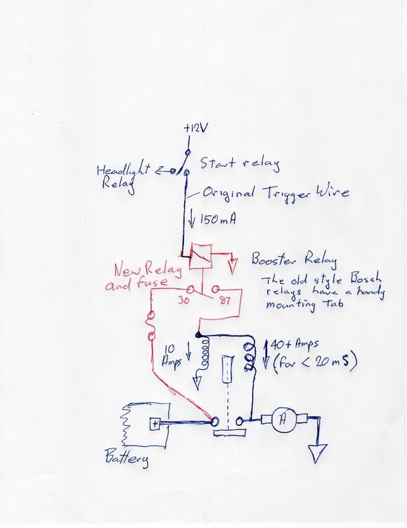
Re the solenoid, I thought an explanation might be helpful.
I show both the coils in the solenoid side by side, each coil has about 300 turns of wire, they are actually one inside the other. The heavy one I call the Grunt coil because it does most of the work engaging the starter is wound on first, the light one I call the Holding coil is wound over the top.
The coils are quite different in resistance, the Grunt coil is only 0.25 Ohms and the Holding coil is 1.25 Ohms so by simple Ohms Law you can calculate the current they draw. Grunt 12 V/0.25 Ohms = 48 Amps, Holding 12 V/1.25 Ohms = 9.6 Amps
The magnetic strength of an electromagnet is the product of current x the number of turns. Grunt 48 x 300 = 14,400 Amp turns, Holding 9.6 x 300 = 2,880 Amp turns so you can see the Grunt coil is magnetically 5 times as strong as the Holding coil.
Note how when the main contacts close the Grunt coil has +12 Volts on both ends, so the current in it drops to zero leaving just the Holding coil to keep the starter engaged. The time it takes for the solenoid to engage the starter gear is quite short, between 15 and 100 milliseconds all depending on how much current you can cram into the coils which is of course dependant on the resistance between the battery and the coils.
If all this has made your eyes glaze over its just the half of it
-
4
-
1
-

(Solved!) Had to get a jump start from roadside assistance; starter motor not cranking after a chilly night; intermitent issue?!
in Technical Topics
Posted
P6X,
That's very thoughtful but I have one question
Since none of the Guzzi schematics show that there are two solenoid coils and the factory only provide a 15 Amp fuse to protect a circuit that can pull up to 60 Amps can you really say they were designed?
I put it to you that the factory engineers don't know there are two coils and they measured the current at the solenoid spade terminal with a multimeter, 10 Amps so lets put a 15 Amp fuse to protect the circuit.
I have measured 60 Amps there but only for a split second. If its not wired right the current is throttled and as a consequence the solenoid only develops a fraction of the pull its capable of and you get the dreaded click.
I also see evidence of the factory thrashing around adding extra relays to try and solve the problem as for example in the later model Griso and Norge 1200s, if they would only draw the coils correctly a light bulb might turn on.
Cheers
Roy