

Kiwi_Roy
-
Posts
2,343 -
Joined
-
Last visited
-
Days Won
61
Content Type
Profiles
Forums
Events
Gallery
Community Map
Posts posted by Kiwi_Roy
-
-
9 hours ago, Tom in Virginia said:
Kiwi Roy, from your V11 Sport schematic ...
"Refer to Test Point Layout drawing for additional troubleshooting info"
Is there another drawing you refer to here, or would it be the schematic presented here?
Having intermittent starting issue with an almost "new" 2600 miles 2002 LeMans and would like to troubleshoot using this schematic. Assume it is also applicable to 2002 LM?
Thanks much for the easily readable/understandable drawing!
Tom in VA
Tom, when I drew the Simple Wiring Diagram I was using my 2001 VII Sport, it had a direct feed to the Start Relay, unfortunately a couple of years later the Guzzi factory switched the Start Relay feed to the ignition switch causing untold grief for owners. You can see the difference here. http://www.thisoldtractor.com/guzzi007/schematics/1999_V11_sport.gif 1999 era with a direct feed to the relay. My 2001 never had a problem with cranking but the regulator Voltage reference was the pits (through two sets of relay contacts).
http://www.thisoldtractor.com/guzzi007/schematics/2004_V11_Sport_Catalytic.gif 2004 with the start relay fed through the ignition switch, I would like to believe the factory are ignorant of the high current the starter solenoid draws but you have to wonder why they haven't spoken to the manufacturer about it some time in the last 50 years. Note this year has a direct connected Voltage regulator, that' should be a plus.
I assume you are having the dreaded click when you press the start button, that is caused by too much Voltage drop through the ignition switch, the starter solenoid is designed to pull at least 40 Amps while it is moving the gear into mesh, once engaged with the main contacts closed it drops to 10 Amps.
The Guzzi schematics never show the double coils in the solenoid, they are both about the same number of turn but one is of heavier gauge wire and draws 5 x the current, thats the one missing on the factory drawings. All Guzzi starters have this double coil even today.
You can probably improve things for a while by cleaning the ignition switch contacts but the real answer is to change the start relay feed from through the switch to direct but that involves changing the headlight relay wiring as well.
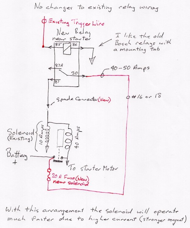
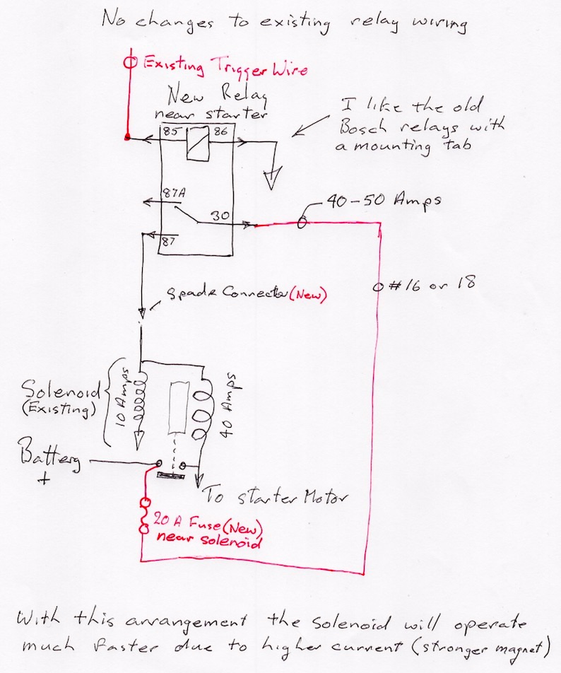
Another easy method is to add a new relay to the existing solenoid trigger circuit to boost the signal the trigger wire is removed from the solenoid and now only picks up the new relay coil, a fraction of an Amp, the new relay contact is fed from a new fuse direct from the battery, it can now provide as much current as the solenoid needs.
You will probably hear about the MPH solution, I don't think that will work with your bike, it would result in the headlight staying On.
I have never actually done one adding an extra relay but it has the advantage in that the original wiring remains the same.
The current of 40-50 amps will only last for about 20 milliseconds (as long as it takes to close the main contacts) then it will drop to 10 Amps while cranking. The current through the motor of course will be 150 - 200 Amps, no change there.
No need for a relay socket, just use spade lugs right on the relay pins.
-
 2
2
-
 2
2
-
-
On 2/4/2012 at 12:51 PM, Slavomir Musilek (R.I.P.) said:
OR...
remove alternator cover, there is a 24mm nut, use 24mm wrench to turn over the crank.
Before doing this remove the plugs. You can also watch marks on flywheel - S for Sinistra (Left) D for Destra (right). Don't forger to check that the pistons are in compresion turn - in TDC the piston should be in its verytop. Check this by putting some soft wooden ply in the plug hole. Also check that the push rods are spinning free.
Voila, you have the piston in TDC and you can adjust yout tappets. Doing the other side is just the same.
Turning the nut in front of alternator seems to me bit more "profesional" and easier that turning the engine by moving the rear wheel, but of course, it is an option too!
Good luck
Slavek
Back from the dead?
You can't argue with that.
-
On 9/9/2020 at 4:49 AM, JKV11 said:
Hello, t have changed the blinkers, because they were not visible enough. I now have standard LED blinkers and a variable flasher relay.
As long as i don't insert a control light, everything works well. As soon as i insert the indicator light the usual problems start. I wonder if i replace the indicator light by two LEDs and i connect the anode with the wires and take the cathodes together and connect them to the mass via a resistance, will this work?
I miss my indicator light

Yes that would work but not so nice as adding two small diodes
LEDs are diodes as well, thats why it only works properly for one direction, if you flip it around it works for the other direction
Add 2 diodes and run it to chassis and the current is always going the right direction through the dash LED, it cannot get to the wrong side lamps because it's blocked by the other diode.
-
2
-
-
On 9/21/2020 at 11:45 PM, JKV11 said:
Hello Roy,
can you tell me or the LED light have a high resistance? If the resistance is at least as high as the original light it will work without any additional diodes or resistance.
Kind regards!
I didn't answer that, yes LEDs usually have a resistance of several thousand Ohms but what's confusing is they also have a forward bias Voltage of around 3 Volts so you can't really measure the resistance with a normal multimeter.
The original incandescent lamp as fitted to the dash resistance is quite low when it's cold, around 100 Ohms from memory.
Some LED blinker lights operate with a very tiny current, I recently helped a Griso owner who's lamps were glowing with the key turned off, the lamps were operating on 40 microamps, that's 0.00004 Amps. On the Griso they use a tiny current to alarm the dash if the normal incandescent lamp burns out, he had fitted LED lamps in the existing lamp holders.
Diodes are the only answer when you want to use a single dash lamp with LED signal lamps, even the tiny current an LED dash lamp draws is enough to operate some LED signal lamps, only the Voltage from the active side gets to the lamp, the path is blocked from the lamp to the other side by the other diode.
BTW if you add diodes you will still be able to use the original dash lamp or an LED
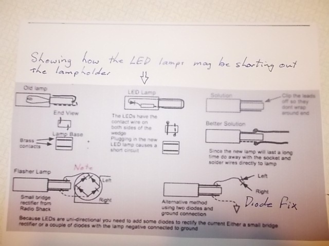
We never did establish if it was the leakage current through the lamp or your new LEDs are actually shorting the lamp holders out.
-
You can sort of figure out the series resistor value of an LED. A small one like an idiot light draws about 10 milliamps (you can measure it), the LED has ~ 3 Volts across it so you need to drop 9 Volts.
9 / 0.01 = 900 Ohms, that would be the minimum in reality it could be much higher like 1-10 K Ohms, you really need to read the specs to figure it out.
Back to the topic
When you put the "controle light" in the socket, does it light at all? If not its shorting the socket out and all four flashers are getting power, this happened to me also, as a temporary fix I snipped one side off the wire contacts.
If the lamps on one side are working correctly but the other side are flashing dimly its because the current the "controle light" draws is enough to make them work, then you need to change the wiring a little as per my sketch No 3, The back to back diodes prevent the signal from going to the opposite side.
Any small diodes will do they only carry a few milliamps the other side of the "controle light" goes to chassis.
I found the old file under the topic Main Switch Fuse Blows
Sorry about the poor resolution, I took a picture of the screen because it was messed up by photo bucket.
-
1
-
-
On 3/17/2019 at 5:32 AM, JKV11 said:
if this is the wirediagram of a V11, can anybody explane why if i have blinkers running lights (so they need no relais), and i replace the controle light with a LED (1,3 M Ohm), all blinkers (L+R) start blinking when ever i activate L of R.
(the relais is replaced by a wire).
Thanks for al idea’s.
I just read through the original post again, I missed the point previously.
When I had a VII I decided to replace the idiot lights with LEDs so I ordered some and stuck them in, turned the key on and a fuse blew.
On investigation the contact on the new lamps shorted out the lamp holders, if you look at the lamps side by side you will see that the contact wires go at right angles to each other. s\So with the LED you are connecting both sides together.
I like to use type 194 lamps to replace the lamp holders, they glue into the shroud then just solder the wires directly onto the lamps, they should outlast the bike.
Lampholders are available for these but they don't work well in the confines of the dash, just solder the wires directly to the lamps
A pair of seizers are a big help when soldering the wires on.
-
On 9/18/2020 at 4:28 AM, docc said:
Good question!

Ha, you stole my picture. That 32mm socket has proven to be really useful.
-
 1
1
-
-
I don't remember any difficulty when I changed the timing chain and tensioner on my VII Sport.
Removing the nut on the crankshaft you need a special deep socket or just go with a 3/4" 32 mm socket and turn to with a wrench.
I don't have a picture of the VII Sport but you should be able to visualize the crankshaft sticking through the socket.
Wrap a few layers of masking tape around the shaft to protect it.
[url=https://ibb.co/HCZfFjV][img]https://i.ibb.co/KDnp0JX/IMG-0534.jpg[/img][/url]
Oops what's happened to the image hosting?
-
On 9/12/2020 at 5:02 AM, Pressureangle said:
If you can touch it firmly for 10 whole seconds, temp is 150* or less. Not a concern. The reg body is a heat sink; most have fins to air cool, some sink to the metal base they're bolted to which is why a clean solid attachment is required.
And don't forget you aren't traveling through the air while idling.
Too hot to touch is not really too hot for modern electronics.
-
A thought occurred to me, has this bike suffered from a meltdown in the wiring, any burnt ground wires around the ECU or the ground wire from the Voltage regulator to battery negative?
Its really difficult to troubleshoot remotely when you are not sure exactly what version of the wiring diagram you have.
-
1
-
-
I think this may be the appropriate wiring diagram Fuse 8 is spare, no electrical petcock
Removing Fuse 1 or fuse 2 or the relays (46) or (49) associated with the ECU should stop the engine do you agree, I think the relays are 4 & 5 in position.
The main interlock through the one way connector (57) to relay (49) coil MUST turn off with the key OR the kill switch, the relay base is a good place to verify that with a test light io chassis.
Click on the diagram to Zoom in.
-
At a first guess I would pull the ignition switch off to see if the wire is not broken and touching behind the switch.
Just undo the two Phillips screws that lets the block drop off.
Refresh the Vaseline while you have it off.
-
2
-
-
A most interesting problem
What year and what model is the bike?
I'm sure there is a simple explanation.
-
1
-
-
Docc,
Are you sure its discharging, my V7iii will sit at 14.7 all day while riding but it drops to high 12s overnight even if disconnected.
Its risky trying to read the leakage current with a multimeter, very easy to blow the fuse in the meter then it will read zero for sure.
One method I use is to connect a small incandescent lamp in series with the meter on milliamp range it will act as a current limit to protect the meter fuse.
-
On 8/7/2020 at 3:57 AM, Mikko said:
yeah, i mentioned that in another post. I upgrade all my wiring on equipment with tin plated marine wire. This company has it for the best price and in stock.
That must be where I read it.
I dont use tin plated wire but I always dip the wire in Vaseline before crimping, it keeps the copper bright.
-
I have never bothered but you can buy wire that is tin plated, they use it on boats a lot so a marine store is a likely source.
I think it would stand up to the conditions in the alternator better,
Docc, can you give us the model No of your regulator so I can look up the connection, there might be something in the wiring instructions that pops out.
Roy
-
1
-
-
The original Ducati Energias drew about 15 milliamps from the reference circuit (headlight) but when the key is off it doesn't draw anything.
My aftermarket direct connect regulator from Electrosport drew 0.3 milliamps all the time On or Off
It should not be possible to get current back flowing from the battery to the yellow wires.

-
Replacing the wires is dead simple but you might need a 40 Watt iron, one with a pencil bit may not have quite enough heat
A soldering gun would have plenty of heat or something like a Weller thermostatically controlled one, there's certainly no nend to replace the stator just because the wires are shot.
Out of interest here is the stator from my V7 Special

-
4
-
-
21 minutes ago, docc said:
Yes, this time I had to to trim the wire off considerably to get it to solder. Not perfect, so I'll be suspicious of it. I did order a replacement from Electrosport that requires a change to spade connectors, but will hold it in reserve for now. Interesting that their product description says, "We incorporated a much nicer strain relief and also install the best quality lead wires that offer much better chafe and heat resistance than the stock wires." (I did apply epoxy to the solder joints for "strain relief" this time, but the anchor for the broken Zip-tie was also broken off. Sketchy "strain relief.")
What should we make of the specification that resistance through each of the yellow output leads to ground should be "higher than 10 MΩ" and my old stator is about 3 MΩ?
They are referring to the insulation resistance 10 MΩ is what you can expect with new wiring but even 0.5 MΩ is perfectly adequate. We don't normally bother with measuring the insulation resistance for 12V wiring but its standard practice for mains wiring its done at a DC Voltage if I recall correctly 1.5 x normal Voltage so it requires a special meter commonly referred to as a Megger, not just a normal multimeter.
If you use new copper wire you will find it solders well to the existing coils.
-
1
-
-
My VII Sport did the same thing, the wire was so corroded I couldn't re-solder it so I simply replaced it with new yellow wires.
-
1
-
-
The sensor gap should be between 0.6 and 1.2mm. Its really hard to measure in situ, this is how I do mine.
Stick a small blob of JB Kwik on the tip and bolt it in place, don't turn the motor.
Allow time for it to set up, pull the sensor out again and measure the thickness of the epoxy.
As for making the sensor oil tight, i'm convinced the oil leaks through the sensor not around it. I took to carrying a spare sensor in the Monkey Paw trap there's absolutely nothing you can do on the road if the sensor fails open.
I don't have a VII any more but I have a two Valve Griso, it can be just as frustrating.
I'm pleased to see some of you are still using the Go Winkie as Docc calls it to instantly troubleshoot a bad contact in the wiring to the ECU relay, I remember finding mine at about half brightness when the stand switch was acting up.
Cheers
Roy
-
2
-
-
You must put those FIAMMS horizontal, any sort of an angle and water gets trapped rusting away the diaphragm
When wiring them use something like #16 direct from the battery with a relay, horns are like high quality speakers they benefit from robust wiring.
And last of all do not mount them to a rigid surface or it damps the noise out, the little metal plate they ship with them has a purpose. They look like they are fixed to the Aluminium plate but if you look closely you will see the thin steel plate below.

-
3
-
-
On 5/3/2020 at 11:40 AM, Grim said:
Can I test the coils on the bike without taking the tank off again?
Yes, pull both plug caps
With your multimeter measure the resistance from each plug cap in turn, it should measure the same resistance typically about 8,000 Ohms, same on both sides. This is a combination of cap, lead and coil in series.
Sometimes Guzzi have used that nasty carbon core lead, it can break contact and cause arcing inside the cable usually misses under acceleration because it's harder for the spark to jump the gap under pressure.
Replace with copper core.
BTW you should not have carbon lead in series with a resistor cap and xxxR resistor plugs, you only need one resistor.
-
2
-
-
On 9/1/2015 at 12:18 PM, danl said:
It is true, I have committed a cardinal sin of motoring - disregarding the oil light! One piece of info I left out was that I had been riding in heavy rain for a while and suspected (hoped) that these two were related. To be clear, I'm not suggesting that anyone make the assumption that an oil light is is due to a bad switch. I took a huge risk, and was relieved that it worked out the way it did.
Combination of heavy rain and dirt or road salt is enough to make the switch track across the insulator, try wiping it with a rag.
WD40 is good for this as well.
Finding TDC for valve adjustment
in Technical Topics
Posted
I wondered how accurate the flywheel is, there are 6 different positions the flywheel can be bolted on, with the trouble owners have finding TDC its highly likely they would bolt it on in one of the other 5, what fun you would have then lol