Kiwi_Roy
-
Posts
2,378 -
Joined
-
Last visited
-
Days Won
62
Content Type
Profiles
Forums
Events
Gallery
Community Map
Everything posted by Kiwi_Roy
-
The problem is this wire has too much resistance, it has to carry the same 30+ Amps peak current as the Red positive wire from the battery back through the regulator to the other end of the stator winding. The Red positive wire can afford a few Volts drop, the Voltage regulator takes care of that but the Black Negative cannot afford any Voltage drop, half a Volt there is taken directly from the battery Voltage Reference. Remember the voltage regulator is hanging on a bracket that's not even grounded properly, just accidentally grounded where the paint scrubbed off. A short wire from the regulator case to a timing cover screw is like a massive cable through the mass of the engine/gearbox to the fat battery ground. It's only the earlier Ducati Energia regulators that need grounding, the later bikes have a direct connected regulator as shown, item (22)
-
That sounds right the headlight relay would close but I don't see how loose magnets would blow a fuse. A loose main battery connection could cause the fuse to blow, the heavy current coil is turned On until the contact closes feeding 12 Volts to the motor armature, I tested that by loosening the positive feed to the solenoid, the fuse blew in less than a second.
-
From my notes, there are two coils in the Valeo solenoid (the old Bosch and the new Chinese starters all have 2 coils as well) One is 1.05 Ohms from the spade connector to chassis by Ohms law that will draw 12/1.05 = 11.4 Amps, this coil is powered up as long as the bike is cranking over. (I call this the Holding Coil, it can never close the solenoid just strong enough to hold it in place) The other coil is only 0.25 Ohms and goes from the spade connector to downstream of the main contact and across the armature. (I call this the Grunt Coil, it does most of the hard work if its wired right that is) The Grunt coil is turned off once the solenoid is engaged. The armature is so close to zero ohms you can ignore that so by Ohms law 12/0.25 = 48 Amps, add the 11.4 and you have 59.4 Amps, in reality you get about 40 Amps. On the later bikes you get Startus Interuptus, the wiring is not up to it so the Voltage drops and the relay just clicks. Solenoid Magnetic Strength: The two coils both have about 300 turns, the magnetic strength is Amps x Turns = 3,420 AT for the first coil, 14,400 AT for the second coil (4 x as strong if its wired right) BTW if you try to measure the currents you cannot do it with a multimeter, the heavy current only lasts for about 50 milliseconds, too quick for a digital multimeter, there are ways of doing it if anyones interested. I have helped dozens of owners with Startus Interuptus, some other models suffer worse e.g. the CARC models that the wire from the relay to the solenoid is really tiny, it would be ok if the current was only ~10 Amps but its a real choke point for 40 Amps, my 07 Griso operated 3 x as fast just by increasing the wire to a No 18. Of course on the later 8 Valve bikes the wiring is even worse, they choked the current through the switch again. I wrote a letter to Piaggio about the problem, they sent me an acknowledgement but I suspect they filed it in the trash.
-
Fuse No 5 on the earlier VII should be a 20 Amp, not a 15. These earlier bikes are better wired in some ways, Fuse 5 is direct from the battery and feeds the Start relay, you should never have a problem with it failing to crank (provided it hasn't blown the fuse). The later bikes late 2003/2004 have the start relay fed from a switched fuse so they suffer from "Startus Interuptus" like many other models, how do I know this, because my 2001 was wired direct. I couldn't understand what SI was about until one day I discovered there are two coils in the solenoid, the solenoid has an inrush current around 40 Amps (too much for a 15 Amp fuse). Trace the wiring to and from Fuse 5 It comes straight from the battery, goes to the Start relay through the normally closed contact to the headlight relay. Compare it to a later model. Here the start relay is fed from fuse 4 via the ignition switch, a 15 Amp fuse will probably never blow because it has half a mile of tiny wire to limit the current and the ability of the solenoid to engage the starter properly. You cannot simply feed the start relay direct or it will turn the headlight on, there's several ways around that.
-
You need to install a Go-Winkie light, it will tell you you have a fault and as you go through the sensors it will tell you when you touch the bad connection. Hot is a broad term, too hot to touch?
-
It's probably in this thread somewhere, the reason for the 30 Amp fuse melting that is. The cause as I see it is too much resistance in the clips holding the fuse, resistance causes heat at a current squared relationship and don't forget the current is pulsing, its not a steady DC but a pulsing DC, the peak is much higher than the average. So saying my VII Sport welded a fuse into the holder but I was able to break it free and clean the socket up again. It never gave me another problem but I eventually replaced the regulator with a direct connect type. Don't re-use a fuse that has overheated toss it and replace with a new one.
-
Its hard to know I can't judge the size, is it possibly the coil for an electric petcock http://www.thisoldtractor.com/guzzi007/schematics/1999_V11_sport.gif item 32 Does the red wire come from Fuse 8? Owners sometimes remove the electric valve and replace with a manual petcock. What is the complete part No we can see just 083
-
Actually the regulator is set for ~ 13.8 Volts, by the time you get some Voltage drop through the headlight relay the battery ends up a little higher say 14.3. If the regulator reference was connected directly to the battery it wouldn't go over 13.8. How do you do that? Either use a dedicated relay or look for another relay that has less load on it. Adding after-market headlight relays will do that also [url=https://ibb.co/4sWhKc1][img]https://i.ibb.co/bH1cQxb/Ducati-Energia-Schematic-w-Notes.jpg[/img][/url]
-
It really doesn't matter which you run to, the battery positive or the live terminal on the starter solenoid, the battery post usually has too many on already and it depends on where you mount the relay, close to the battery or close to the starter Not the one that connects to the starter motor, the one that connects to the battery. Here are the drawing files, but no perving at Carl's girlfriend mind you. Scroll down without looking! http://www.thisoldtractor.com/guzzi007/sportissimo.html
-
I wondered how accurate the flywheel is, there are 6 different positions the flywheel can be bolted on, with the trouble owners have finding TDC its highly likely they would bolt it on in one of the other 5, what fun you would have then lol
-
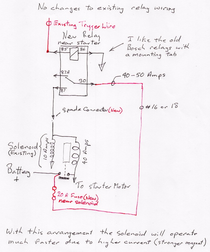
Tom, when I drew the Simple Wiring Diagram I was using my 2001 VII Sport, it had a direct feed to the Start Relay, unfortunately a couple of years later the Guzzi factory switched the Start Relay feed to the ignition switch causing untold grief for owners. You can see the difference here. http://www.thisoldtractor.com/guzzi007/schematics/1999_V11_sport.gif 1999 era with a direct feed to the relay. My 2001 never had a problem with cranking but the regulator Voltage reference was the pits (through two sets of relay contacts). http://www.thisoldtractor.com/guzzi007/schematics/2004_V11_Sport_Catalytic.gif 2004 with the start relay fed through the ignition switch, I would like to believe the factory are ignorant of the high current the starter solenoid draws but you have to wonder why they haven't spoken to the manufacturer about it some time in the last 50 years. Note this year has a direct connected Voltage regulator, that' should be a plus. I assume you are having the dreaded click when you press the start button, that is caused by too much Voltage drop through the ignition switch, the starter solenoid is designed to pull at least 40 Amps while it is moving the gear into mesh, once engaged with the main contacts closed it drops to 10 Amps. The Guzzi schematics never show the double coils in the solenoid, they are both about the same number of turn but one is of heavier gauge wire and draws 5 x the current, thats the one missing on the factory drawings. All Guzzi starters have this double coil even today. You can probably improve things for a while by cleaning the ignition switch contacts but the real answer is to change the start relay feed from through the switch to direct but that involves changing the headlight relay wiring as well. Another easy method is to add a new relay to the existing solenoid trigger circuit to boost the signal the trigger wire is removed from the solenoid and now only picks up the new relay coil, a fraction of an Amp, the new relay contact is fed from a new fuse direct from the battery, it can now provide as much current as the solenoid needs. You will probably hear about the MPH solution, I don't think that will work with your bike, it would result in the headlight staying On. I have never actually done one adding an extra relay but it has the advantage in that the original wiring remains the same. The current of 40-50 amps will only last for about 20 milliseconds (as long as it takes to close the main contacts) then it will drop to 10 Amps while cranking. The current through the motor of course will be 150 - 200 Amps, no change there. No need for a relay socket, just use spade lugs right on the relay pins.
-
Back from the dead? You can't argue with that.
-
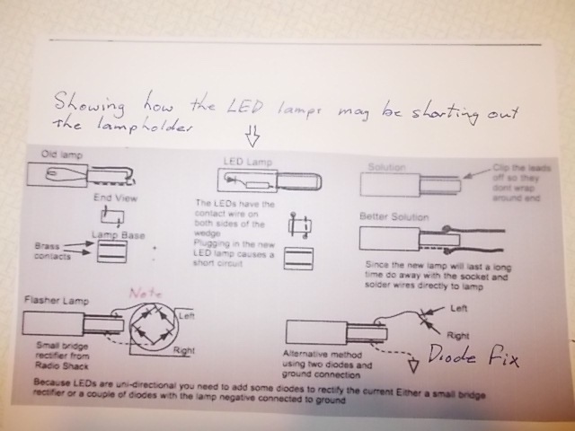
Yes that would work but not so nice as adding two small diodes LEDs are diodes as well, thats why it only works properly for one direction, if you flip it around it works for the other direction Add 2 diodes and run it to chassis and the current is always going the right direction through the dash LED, it cannot get to the wrong side lamps because it's blocked by the other diode.
-
I didn't answer that, yes LEDs usually have a resistance of several thousand Ohms but what's confusing is they also have a forward bias Voltage of around 3 Volts so you can't really measure the resistance with a normal multimeter. The original incandescent lamp as fitted to the dash resistance is quite low when it's cold, around 100 Ohms from memory. Some LED blinker lights operate with a very tiny current, I recently helped a Griso owner who's lamps were glowing with the key turned off, the lamps were operating on 40 microamps, that's 0.00004 Amps. On the Griso they use a tiny current to alarm the dash if the normal incandescent lamp burns out, he had fitted LED lamps in the existing lamp holders. Diodes are the only answer when you want to use a single dash lamp with LED signal lamps, even the tiny current an LED dash lamp draws is enough to operate some LED signal lamps, only the Voltage from the active side gets to the lamp, the path is blocked from the lamp to the other side by the other diode. BTW if you add diodes you will still be able to use the original dash lamp or an LED We never did establish if it was the leakage current through the lamp or your new LEDs are actually shorting the lamp holders out.
-
You can sort of figure out the series resistor value of an LED. A small one like an idiot light draws about 10 milliamps (you can measure it), the LED has ~ 3 Volts across it so you need to drop 9 Volts. 9 / 0.01 = 900 Ohms, that would be the minimum in reality it could be much higher like 1-10 K Ohms, you really need to read the specs to figure it out. Back to the topic When you put the "controle light" in the socket, does it light at all? If not its shorting the socket out and all four flashers are getting power, this happened to me also, as a temporary fix I snipped one side off the wire contacts. If the lamps on one side are working correctly but the other side are flashing dimly its because the current the "controle light" draws is enough to make them work, then you need to change the wiring a little as per my sketch No 3, The back to back diodes prevent the signal from going to the opposite side. Any small diodes will do they only carry a few milliamps the other side of the "controle light" goes to chassis. I found the old file under the topic Main Switch Fuse Blows Sorry about the poor resolution, I took a picture of the screen because it was messed up by photo bucket.
-
I just read through the original post again, I missed the point previously. When I had a VII I decided to replace the idiot lights with LEDs so I ordered some and stuck them in, turned the key on and a fuse blew. On investigation the contact on the new lamps shorted out the lamp holders, if you look at the lamps side by side you will see that the contact wires go at right angles to each other. s\So with the LED you are connecting both sides together. I like to use type 194 lamps to replace the lamp holders, they glue into the shroud then just solder the wires directly onto the lamps, they should outlast the bike. https://www.superbrightleds.com/moreinfo/miniature-and-subminiature-bulbs/194-led-bulb-1-led-miniature-wedge-retrofit-car/197/ Lampholders are available for these but they don't work well in the confines of the dash, just solder the wires directly to the lamps A pair of seizers are a big help when soldering the wires on.
-
Ha, you stole my picture. That 32mm socket has proven to be really useful.
-
I don't remember any difficulty when I changed the timing chain and tensioner on my VII Sport. Removing the nut on the crankshaft you need a special deep socket or just go with a 3/4" 32 mm socket and turn to with a wrench. I don't have a picture of the VII Sport but you should be able to visualize the crankshaft sticking through the socket. Wrap a few layers of masking tape around the shaft to protect it. [url=https://ibb.co/HCZfFjV][img]https://i.ibb.co/KDnp0JX/IMG-0534.jpg[/img][/url] Oops what's happened to the image hosting?
-
And don't forget you aren't traveling through the air while idling. Too hot to touch is not really too hot for modern electronics.
-
A thought occurred to me, has this bike suffered from a meltdown in the wiring, any burnt ground wires around the ECU or the ground wire from the Voltage regulator to battery negative? Its really difficult to troubleshoot remotely when you are not sure exactly what version of the wiring diagram you have.
-
I think this may be the appropriate wiring diagram Fuse 8 is spare, no electrical petcock Removing Fuse 1 or fuse 2 or the relays (46) or (49) associated with the ECU should stop the engine do you agree, I think the relays are 4 & 5 in position. The main interlock through the one way connector (57) to relay (49) coil MUST turn off with the key OR the kill switch, the relay base is a good place to verify that with a test light io chassis. Click on the diagram to Zoom in.
-
At a first guess I would pull the ignition switch off to see if the wire is not broken and touching behind the switch. Just undo the two Phillips screws that lets the block drop off. Refresh the Vaseline while you have it off.
-
A most interesting problem What year and what model is the bike? I'm sure there is a simple explanation.
-
Docc, Are you sure its discharging, my V7iii will sit at 14.7 all day while riding but it drops to high 12s overnight even if disconnected. Its risky trying to read the leakage current with a multimeter, very easy to blow the fuse in the meter then it will read zero for sure. One method I use is to connect a small incandescent lamp in series with the meter on milliamp range it will act as a current limit to protect the meter fuse.
-
That must be where I read it. I dont use tin plated wire but I always dip the wire in Vaseline before crimping, it keeps the copper bright.