
Lucky Phil
-
Posts
5,450 -
Joined
-
Last visited
-
Days Won
276
Content Type
Profiles
Forums
Events
Gallery
Community Map
Posts posted by Lucky Phil
-
-
8 hours ago, p6x said:
Compliments on the ingenuity and inventiveness...
I fully understand the modus operandi, and the how to get to it... alas, I do not have access to the tools and paraphernalia required to mimic your installation.
I am going to have to come up with something that requires much less involvement.
I am going to purchase the clock and devise something that will most likely not be as elaborated as your installation.
Thanks for sharing though...
A più tardi!
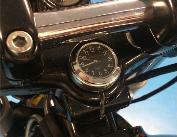
I think that there's not that many options on the V11 to mount that particular clock size in a position that looks neat and tidy. The spot I chose was a bit of a last resort. You can of course just use double sided 1mm thick tape but the domed top on the triple clamp even makes that a little difficult without turning it flat.
On my Interceptor I just used the tape mount system although the top nut is pretty flat on that.
Ciao
-
 2
2
-
-
3 hours ago, p6x said:
I am interested in finding out how you bolted it in.
The Formotion website indicates the clock is sold with a mounting bar, but since it is not visible in the pics you included I am intrigued.
I was worried someone might ask this.
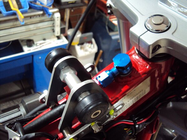
I wanted the clock mounted some other way than a Velcro sticky pad or a double sided pad so I made up the following.
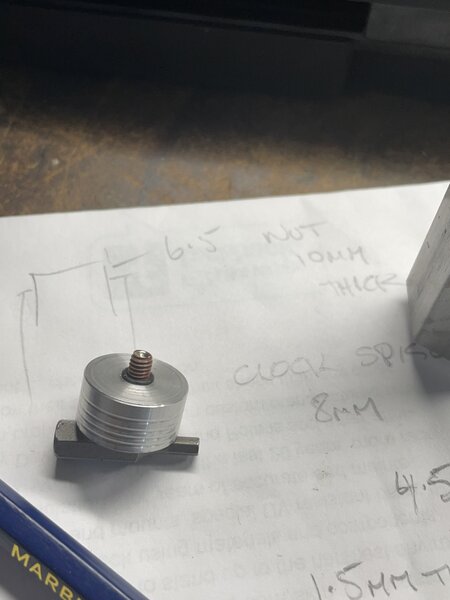
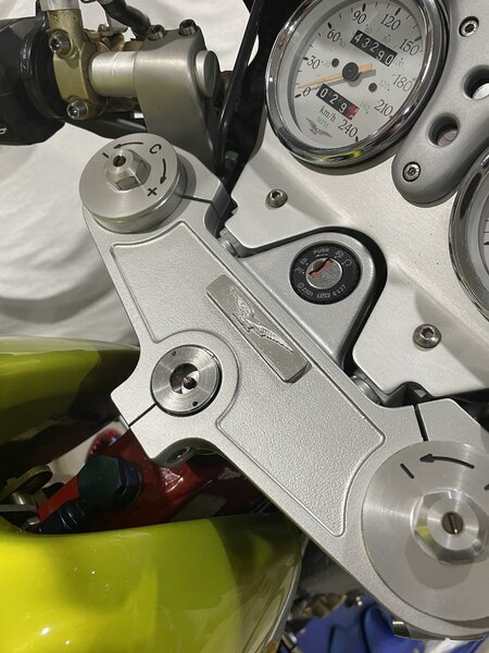
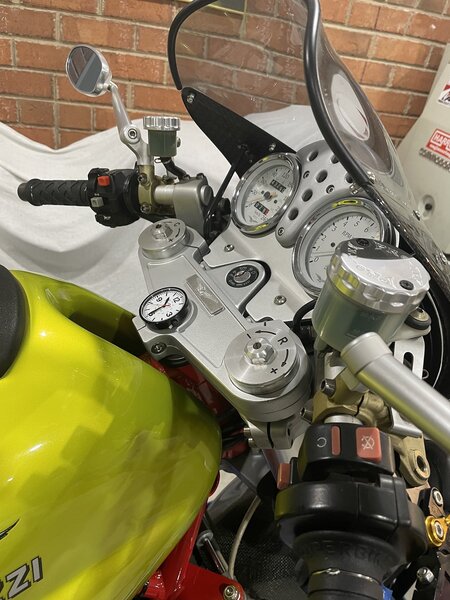
This aluminium plug is a slight interference fit in the steering stem tube and is tapped in with some locktite on it to the required depth. The cap screw in the ctr is held in place by a rubber oring so it doesn't fall out when the clock isn't installed. So the cap screw head faces downwards and can be accessed from the bottom of the lower triple clamp up the hollow centre with quarter drive extensions and a 3mm allen head bit.
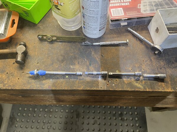
So because you cant get a single long extension up the steering stem tube with the front wheel on you feed 4 short extensions up there as you go. The bit holder on the end has a collar I made to centralise the holder in the centre of the tube so its a simple task of feeding the extensions up the tube and connecting them 1 at a time and when the 3mm bit arrives at the allen head screw just twist it until it drops into the head. Simple and easy as the tool is centred and all you need to do is apply upward pressure and rotate until it engages.
With the triple crown nut I machined it down until it was 1mm above flush with the top of the clamp and drilled out the std hex hole round to locate the spigot on the back face of the clock. With the hex drilled out you need a way to install and tighten the top nut now so I drilled 2x 3mm holes which you use a pin wrench on. The pin wrench is the small brass tool in the image above. The object was to have the clock as close to the top surface of the triple clamp as possible but the holding force of the fixing screw was taken by the spigot on the back of the clock so the fixing screw wasn't trying the pull the spigot out the back of the clock rear cover.
So here it is ready to slip the clock into the locating hole with one hand and with the other on the ratchet and extensions tighten it down. Easier to do than it sounds. If you had the front wheel and fender off it would just need 1, 12" 1/4 drive extension and the ratchet.
Yes I know, sanity is in short supply here.
Ciao
-
3
-
 1
1
-
 2
2
-
 1
1
-
-
32 minutes ago, p6x said:
the valve number corroborates Lucky Phil's statement that he does not have the issue with the four valved Daytona.
When it comes to design, I am pretty sure none of the European motorcycle companies simulated extreme weather conditions to confirm their criteria.
Ducati has a lot of experience in fuel injection control. Maybe we should get them involved for a replacement ECU on our V11 Guzzi? https://www.ducatienergia.com/media/products/140128-1710-efi.pdf
If you look at the last page of their presentation, they include an air temperature sensor, and an absolute air pressure sensor.
You might be very surprised at the lack of science put into the mapping and how loose the process is. One particular late model Guzzi when you look into the software it's obvious they started with a Ducati map because it's notated in the ID details. They didn't even bother to change it as only people digging deep into the software would find it. So you go to WM and want a map for your latest model and they just dig out maps from another customer with a similar engine design and capacity and start there. Fair enough but you do wonder sometimes how interested they really get in making it run really nicely. I also had a couple of Triumphs T595's back in the late 90's and they ran the French Sagem system. The factory released plenty of software updates to correct things like random stalling when stopping at the lights and other stuff. I thought it must be terribly hard to rectify this stuff then my friend installed a Motec unit on a customers bike and had the Triumph running and carburetting absolutely perfectly after about 30 min on the dyno. So an injection system manufacturer and a motorcycle manufacturer couldn't do what a talented guy in his own business could achieve in 30min. Sometimes the big wheels turn so slowly they just grind to a stop.
Ciao
-
3
-
-
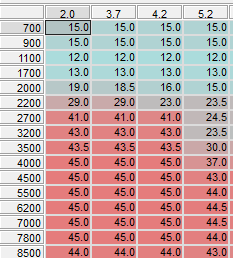
I just went and looked at a std v11 2000 fuel and ignition maps and one interesting thing is around that RPM and probable throttle opening there is a large step in the ignition advance. So 2700-3200 rpm and 4.2-5.2 deg throttle which is kind of in the area of issue. The advance change is interpolated between these cells of course and maybe I'm wrong but possibly this area of change combined with engine temp and OAT play a part. If I still had the 2 valve fitted I could have a play but of course when you want it to hickup it never does.
Ciao
-
1
-
2
-
-
22 minutes ago, p6x said:
I am experiencing the same.
I have perfect idle. No fluctuation at all.
My 04 Le Mans was immobilized since the beginning of June this year, waiting on a bar end weight.
Prior to that, the bike was running properly.
Yesterday, I took the bike out around 90 degF, felt temp 99 degF because of the humidity, and when keeping steady rpm to respect 45 mph, I got some sputter. Not permanently, but recurrent. If I open the throttle, it goes away.
Prior to my June cold storage, I had never had any kind of sputter when maintaining steady RPM. However the air was cooler.
I have read the FAQ topics:
-TPS Setup and TBT
-Decent Tune up
-V11 ECU diagnostics and reprogramming
and this one: Set you V11 CO Fuel trim
Could I get away with simply changing the CO fuel trim by trial and error?
My main problem, is that I cannot make sense of having the injection sputter when I keep the same rpm constant. All the parameters fed to the ECU remain the same; so there should not be any reason for it to get confused. Or is my assumption wrong?
I am aware that quick changes in RPM are usually the source of sputter, as the ECU may lag a bit in adjusting to sudden revolution increase. But on a steady input, why would the fuel regulation miss?
The sputter I experience is always around 3000 rpm, or below. It does not seem to happen once you go beyond 3k.
It's a question that has been around as long as the bike and experience by many including myself. I don't know of anyone having an answer to it. Some suggested wear in the cam chain affecting the ignition pickup but mine still did it after I upgraded to gears. My experience is the same as your and it appears to come and go with changes in OAT. If I still had the 2 valve engine in the bike I would be experimenting with fuel mapping via Tunerpro in the affected area and the engine temp break point maybe. The Daytona engine doesn't have the issue.
Ciao
-
1
-
1
-
-
34 minutes ago, docc said:
Are we trying to "get an order up" for Joe to do a run?
I'm in discussions with Joe now on the design of a new oil pump along with Dynotec and I'd suggest anyone interested in new gears in the future get a group together now and get him do a run. His Gear maker isn't getting any younger and it's a bit of a labour of love as well so the availability of these things won't necessarily stretch into the long term horizon. I've got another set of Daytona gears coming at the end of the year for a 95mm bore engine I want to build as well as the new design oil pump.
Don't want to sound too pessimistic but recent circumstances have focused me on the utility of acting sooner on things rather than later.
Ciao
-
3
-
-
2 hours ago, p6x said:
Thanks!
I don't have a buff, but I know where to find one not far away. I will try your suggestion. And if it looks too different, I can always do the powder later.
The originals look to be "blued" to me, same as the finish on a gun but polished first. You can buy bluing kits and do it at home as I did with the frame side plate bolts and a marking out tool I restored in a thread here somewhere.
Ciao
-
1
-
-
48 minutes ago, Pressureangle said:
Docc, I don't know about the V11 vent system. The 'Sport rear takes 250cc, I used Lucas 80/140 'super duper high performance' gear oil, with about a tablespoon of Jet-Lube open gear and cable grease, which appears to be pure Moly with enough grease to make it stick to stuff-I use that on the spliney stuff.
So, after ~20 miles of "3 miles in the middle was 80-100mph" The housing temp was 116*F after 5-6 miles home @ 35mph.
But yay, there is no trace of oil at the tip of the bleeder, I didn't even put a hose over it so I could be certain. Saturday I'll go beat it up where I can hold 70-100 for 1-15 miles, and take the temp gun with me.
I know y'all have recorded drive temps, what's the norm? 116*F isn't even worth talking about in automotive axles.

You could replace the big and bulky rear drive torque arm with an aftermarket unit with rod end fittings which would give you a lot more room to play with the vent solutions. Your oil deflector of some sort seems like a good idea.
Ciao
-
1
-
-
11 hours ago, Grim said:
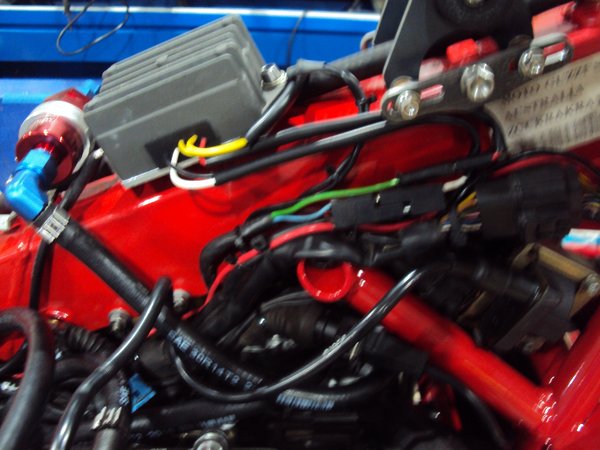
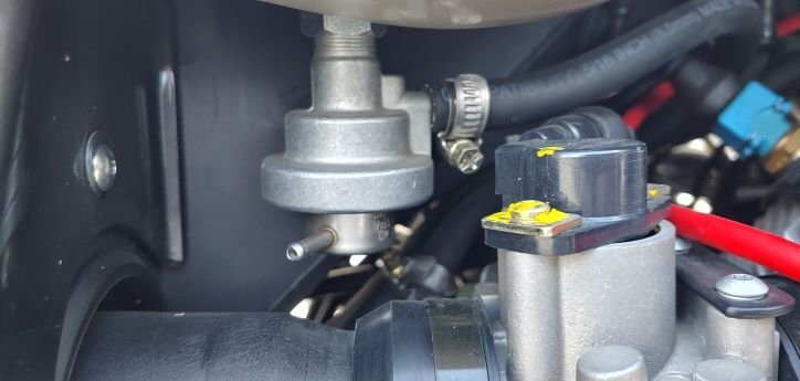
I like the shiny blue banjo...
On pre-pump in tank bikes the hose has to bend round the fliter at a wired angle too, so it hits the airbox at an angle.
Yes mine doesn't have that now. I spaced the regulator up a few extra mm so the vent hose now runs under it and has a straight shot at the airbox. You can just see it in this image passing under the regulator and fuel filter.
Ciao
-
1
-
-
22 hours ago, gstallons said:
The quality of rubber used making the hose . You will notice there is not even thread woven into the hose !
You can blame MG , the vendor that makes the hose , whoever you want . It is NOT Japanese (QUALITY) rubber .
I just used 8mm EFI hose on mine. Even plain rubber hose is fine, it carries no pressure, it's just a vent hose. Same for the big hose from the crankcase breather. They seem to last about 5 years or so before they start to perish. They are in a hot environment.
Ciao
-
Whatever happened to the "right price" being "whoever drags it out of my sight and doesn't charge me to do so". Seems to me what it's worth in the harsh light of day. Maybe a case of beer, cheap beer that is. Valuing old shitters like this is about what you want it to be. A part it out exercise, full resto, old rat bike, what? and of course the hidden mysteries within.
Ciao
-
 3
3
-
1
-
-
5 minutes ago, leroysch said:

Inspected the plugs, intakes...cleaned out the sump and strainer...and got around to cleaning the air box which had been laying on the bench. I was surprised by the amount of fluid which had pooled inside (~ 1ml or so) and got curious. Looks like the air box has a false bottom ending near the aft end. In any event set this up to help mop up whatever cares to dribble down. Will rotate it 180 degrees and see if anything comes out from below the false bottom. I know, OCD...but might as well satisfy my curiosity while it's off the bike...
Pull the inlet trumpets out and get your hand or a rag on a stick in there and give it a good clean out.
Ciao
-
2
-
-
13 minutes ago, Tom in Virginia said:
'02 V11 LeMans, all original, no mods. Bone stock collector bike with 2400 miles when I purchased last summer.
Question: I noticed on the right side of fuel tank an open ended tube. Not sure what is going on here. The '03 LeMans has entirely different fuel delivery setup. Should I vacuum cap this open ended tube or is it a vent to atmosphere?? Thanks in advance.
")
Under no circumstances cap that port off. The fuel map is designed to meter fuel at a pressure dictated by the regulator which controls that pressure via a bladder with spring pressure on one side and atmospheric pressure on the other. Plugging the vent will seal the bladder from atmospheric pressure and affect the delivery pressure. It was originally used on other applications to regulate fuel pressure to inlet pressure but everyone abandoned the idea early in the piece. The very first injected ducati 851's used it but then discarded the connection.
Ciao
-
6
-
-
41 minutes ago, Gmc28 said:
Phil, what did you use as the medium/liquid?
I picked up one of these this winter, but haven’t used it yet. Was thinking the flat slide would be a good candidate.
A little bit of simple green or C18 truck wash. you dont need much around 3% is enough. I used petrol with some injector cleaner to clean the injectors in my small jewellery ultrasonic bath. I also had it connected up to a 6volt battery supply to hold the injector open while it was cleaning.
It was such a dodgy thing to do (outside in the full open air I might add) I stood by with a fire extinguisher the whole time. I was thinking as it was working that this is the sort of practice that ends up on the nightly news. I'm making a home made safe injector cleaner now.
Ciao
-
4
-
1
-
-
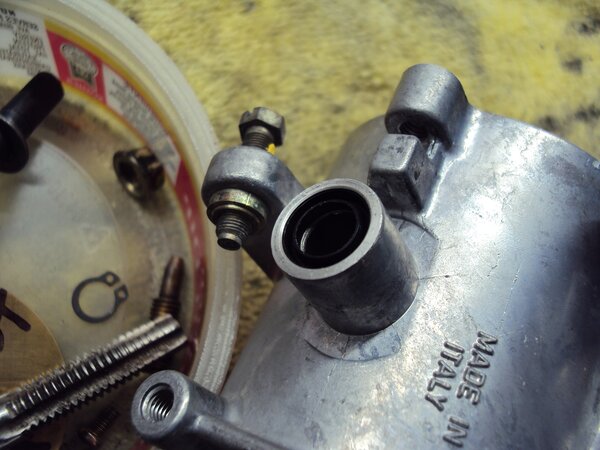
After recently rebuilding 3 throttle body sets I use one of these. I've 2 one large 20Litre one and a small one for, well small stuff. Forget the toxic spray and soak junk these work perfectly esp for things like throttle bodies.
Here's what a 25 year old second hand covered in grunge throttle body looks like after 30min in the ultrasonic tank. Plus all the internal passages are clean as well.
Ciao
-
2
-
2
-
-
2 hours ago, footgoose said:
We've got a thread on this problem here back a year or so. Yes they do fill with crud over time. Was it member antmanbee that flushed his frame with kerosene ?
I wouldn't recommend that personally. Unless there is debris clogging something all you do is loosen up stuff you don't want to. The drain line is via a banjo fitting anyway so it's a horizontal inlet the the pipe so contaminants don't tend to enter unless there's a LOT of stuff, usually rusty stuff in the spine.
Ciao
-
1
-
-
1 hour ago, red lion said:
1997 1100 sport runs strong and pulls hard, air box removed now has K&N filter pods, but the bike has a miss now and then, also dies at stop signs some times. It has new spark plugs, new fuel filter, clean air filters. I"m thinking that it might be the fuel pump. Any thoughts what to do?
Not surprised it has some running issues.
Ciao
-
1 hour ago, docc said:
These observations make me suspect that the inside of our frame spines, that are supposed to drain the liquid oil portion of our crankcase breather, can become compromised (clogged or restricted) and force more crankcase breather oil through the left side of the airbox.

Nothing works perfectly docc it's a pretty crude system so some oil vapour still gets in the airbox and condenses over long periods of time. Who here periodically gets in and wipes out the airbox interior?
Ciao
-
2
-
-
1 hour ago, docc said:
Is it wet around the outside of it, or is all that oil coming from the crankcase venting and trying to get out from inside the airbox on the left side?
Thats my suspicion docc. The breather into the airbox is also on the Left hand side as well.
Ciao
-
1
-
-
3 minutes ago, docc said:
This is really interesting. My right side airbox boot is totally dry and my left is scuzzy with oily deposits and accumulation like @leroysch shows. Yet all of the "bell housing" area leaks, including the nefarious crankcase vent tube have been seen to on my Sport in the last couple years. Something is escaping us?

Yes docc, your bike like many is breathing oil into the airbox and it ends up on the LHS because that's the side it leans on due to the LHS side stand.
Ciao
-
1
-
-
9 hours ago, Grim said:
Hi, thought I would give it another go, found the idle dropped to 1000 at 521mv with the air screws closed.
Anyone else using this map, is it ok just just set the idle where I want it (C1100) using the left idle stop screw and not worry about the MV going up?
..Cylinders are in sync at idle and 3k.
Thanks
The idle MV setting is a "guide only" not a specific requirement. It's only so you can set the idle screw to a start point after you've had the Butterflys fully closed to set the TPS and have a rough idle position to begin the tuning process.
Ciao
-
2
-
2
-
-
He needs to remove the air filter and look INSIDE the airbox at the airbox floor, not just at the filter.
Ciao
-
4
-
-
24 minutes ago, jetboy said:
yeah, that is truly in the cards at this point. Yes, new phase sensor, fuel pump, petcock(manual) - I thought the fuel filter would be the no brainer change but maybe because mine is a 2000 or I just ordered wrong. (or it has been retrofitted at some point).
problem is I am ia tiny town of only ~200 people so its not like a thing I can just go grab. But gas poured out of it. both ways, seeminly with no problem or resistance.
One question: The fuel return line has a tiny vacuum nipple to activate it and I just have it open... hmmm. where does that vacuum line go? could that be the issue?
The port to nowhere is what it is. It just senses atmospheric. Used to sense intake port pressure in other applications in the early days on Ducati's for example.
If its running rich as hell all of a sudden then about the only thing that can cause that is a stuck fuel pressure reg. I've not personally seen one fail but if you leave them to dry out they do tend to stick closed. You can hear the pump load up and suddenly there's a pop as it unsticks off it seat.
I bought 2 phase sensors about 18 months ago for 10usd each from China. Seems to work fine and indistinguishable from factory model. If you look at aftermarket suppliers in the automotive world that sell thousands of these for cars which they have commonality they generally charge around $50 or so for them and I can guarantee they will be Chinese versions as well. I put the info on here at the time.
Ciao
-
1
-
-
32 minutes ago, po18guy said:

As I said too many digits for a part number. The position and qty aren't a constituent of the part number. Nor is the GU in the majority of parts systems including Guzzi dealer systems.
Ciao
Header Pipe cleaning
in Technical Topics
Posted
Interesting. Go to 6:45 for stainless exhausts.
Ciao