Camn
-
Posts
154 -
Joined
-
Last visited
-
Days Won
4
Content Type
Profiles
Forums
Events
Gallery
Community Map
Everything posted by Camn
-
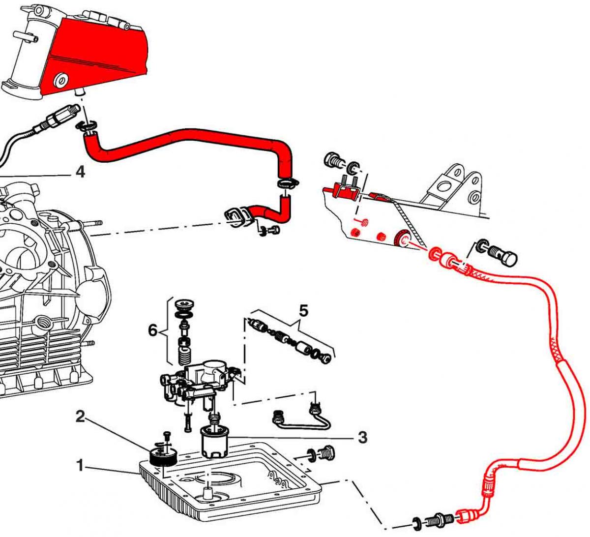
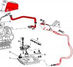
Isn’t it so that the breathing system of V11 is among the best in Guzzis? Oil fumes travel with the ”breathing air” along the large breather pipe up, to the upper part of the (spine) frame. The frame tube is hollow, and works as a liquifier. The main part of the small oil drops in the oil fumes are separated. The air, is directed to the suction box and from there, to motor with the intake air (a part of this oil stays on the bottom of the suction box). The separated oil flows with gravity inside the main frame tube to the bottom of it, and from there, along this small pipe (which was the quesiton), back to the sump. But why there is no ”one way valve” at the breather pipe outlet on V11? Many other models with the 2V big block do have it… maybe because of the breathing system itself...
-
At first I was: ”but all the V11:s have PF3C” – what does he mean, Meinolf if somebody, should know better... But after checking from GuzziDiag -files => of course there are some models, where there is the 15RC ecu and PF1C tps combined (Breva 750, Nevada Classic 750, Nevada Classic 750 S.E, Nevada 750 S, V7 Classic, V7 Cafè, and early V7 Racer) - he takes the look up table from a BIN -file of one of these... clever. If I understand this right, this will be really cool. Since the PF1C does not have oval screw holes, it cannot be adjusted => how to reach the basic setting of 156 mV (the right value according Meinolf )? There will be a way to tell with GuzziDiag to the ecu => "now, with this mV tps value, the throttle flap is on the zero opening position (not idle position)". But if you have sandard maps on your ecu, how do you find the idle position after this...(for example 465mV for ”no kat” models or 550mV for ”kat” models) when GuzziDiag (ecu) cannot dispaly values accurate enough for this ?
-
Here also same cure. The leak was at the back flange of the gear box. Oil dripping, when the bike was standing still.
-
Parts marked "LMT-S" (LeMans Tenni/Scura) 2001-2002: Clutch cpl. GU 01080140 Clutch disc GU 01084440 Disc GU 01081940 Belleville spring GU 01084040 Flywheel GU 01067040 (Standard 2-disc flywheel cpl. "LM-SN" GU 04067000, LeMans/SportNaked) Chain ring cpl. GU 01068040 Pin GU 01067540 Spacer GU 01067640
-
Interesting... I have a spare part book which includes among others, Scura and Tenni (but not Rosso Mandello). For Scura and Tenni the part numbers (single plate clutch) are the same.
-
My numbers (just notes from different forums): LeMans Tenni 170, Rosso Mandello 300, Scura 700 = 1170.
-
The later V11's have the "Shindengen" (shunt type?) regulator. Do these V11's have problems with the 30A fuse, as we with the "Ducati" regulator do? I have had this year a LiFePo -battery installed, and I believe it makes things worse in combination with the Ducati Energia regulator, because it can take a lot of current in the beginning (but you save 4 kg:s of weight).
-
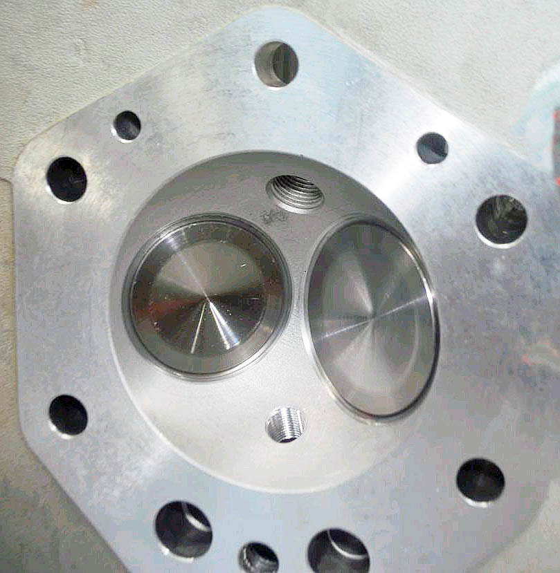
Very interesting... I would very much like to see how different are the internals... and how does the fixing point of the original fly wheel looks like...
-
Meinolf is a “heavy user” and takes it for granted, that we all know the GuzziDiag/Tunerpro -details and change the charts in our ecus very often… To see and change the tps look up table, all the basic steps have to be taken. - read the *.bin -file from your ecu (for 15M the IAW15xReader) - open TunerPro and select the right XDF file (15M/V2.28), open the *.bin file in TunerPro - rework the tps look up table with TunerPro and store the new *.bin file - write the new *.bin file to your ecu (for 15M the IAW15xWriter) The columns... 0-1-2-3 … F and 0.0-1.0-2.0 … 0.0 ?
-
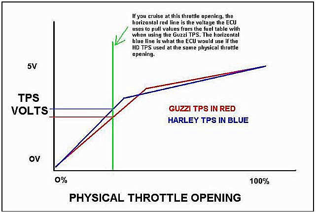
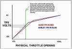
The curve of the Harley tps is not the same as the curve of the PF3C. Since Cali and V11 use the same PF3C, I can not see any reason, why the tps of cycleworks should not work on a V11, I understand that they send a nice test curve with each tps. It would be interesting to know why they write like that on their website, a mistake? (the picture is from some Guzzi -site, I have no note where I took it from)
-
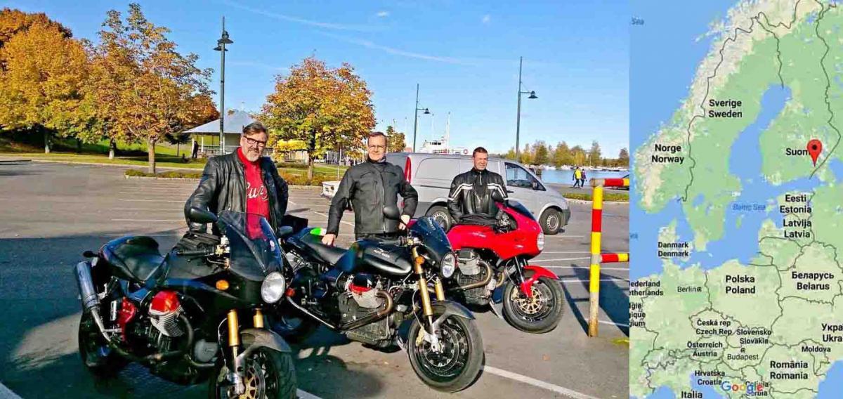
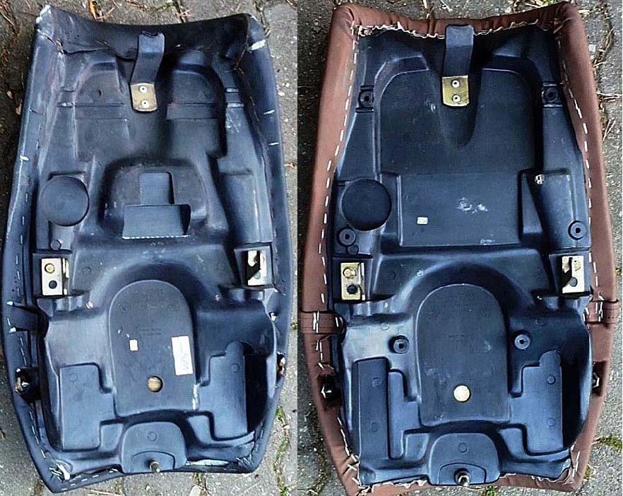
Thank you Lucky Phil for the idea and Chuck for the hard work. A long way from Texas Elwood, but here you can see three happy "extender mod - batch one" part owners (Nero Corsa, Scura, LeMans).

-
Took some photos, bought this year, made in... "a night in Tunisia"
-
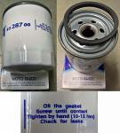
It is printed on the UFI filter. I have saved this from the German V11 site (translation into English my own): “ Tightening torques exist for the UFI filter. The old one (8 layer) 12 Nm, the new one (14 layer) for the Carc models 15 Nm. On both of these filters the on printed tightening torque is 10-12 Nm. To change the filter, you need a filter tool and if possible, a torque tool. Up till 2009 there were oil leaks because of an imperfect seal. Mainly on Norge, Breva, Griso 850/1100, 1200Sport2V, Bellagio and Cali Vintage. Guzzi recommends according the training material from 3/2010 to replace the gasket of the filter with a new gasket Cod. 981115. This gasket has the same measurements, but the material has different properties. If the manufacturing date of the filter is before 2009, the gasket needs to be changed. “
-
Very interesting measurements. Last summer I tried the most extreme: I dropped the triplets as much as possible (18 mm more than the factory setting) plus had the sag adjusted to maximum. Rear sag to minimum. The idea was to try, if I could move more weight to the front. The tendency to wobble at high speed did not change for better. At least not very much. The steering was clearly easier on curvy roads, I liked that a lot. But the result was that the “free space” between the oil pan and ground was reduced. The side stand took a good hit on asphalt…and there we went… (when training cautiously on a track). My experience was, that for normal driving – I liked it a lot. For practicing on track – you should be more experienced (than me, to know how much lean over). The RSV Mille was mentioned. RSV 1000 Technical Training Course 7/1999: "The RSV Mille is the best production line bike for use on the track. Dry weight 189 kg, optimally distributed with 49.2% on the front axle and 50.8% on the rear axle.” V11 46/54%, RSV Mille 49/51%, both values from the first production model from 1999 (Mille obviously with original parts, the muffler weighs a ton...).
-
The education from Kiwi_Roy about the functioning principle/wiring of the Ducati Energia Regulator has alarmed me... I have had also the Odyssey for some years now. The 30A Fuse likes to melt and the coils of the relays tend to be quite warm (when feeling with finger on top of them). It says on my Odyssey PC545: “Cyclic charge voltage 14,4-14,8V” (weight 5.7 kg/12.6 lbs). The Guzzi Workshop Manual, where the Ducati Energia Regulator is covered says: "The regulator has been calibrated in order to maintain the battery voltage at a value between 14÷14.6 Volts." So, shouldn't it match... (if the reference voltage is right for the Ducati Energia) Now I installed a LiFePo battery (Unibat XRacer Lithium 12, 24Ah, 380 CCA, 1,7 kg/3,7lbs). It must be charged between 14-15V. Although they write from the Ducati Energia Regulator: „NOT COMPATIBLE WITH LITHIUM IRON BATTERIES AS SUPPLIED BY SHORAI. USE OF DRY CELL DESIGN AND LITHIUM IRON BATTERY NOT RECOMMENDED, OR SUPPORTED FOR WARRANTY.” http://www.euromotoelectrics.com/product-p/edl450-voltrect.htm. ... I measured with the LiFePo battery: Motor off: 13,6V. 1000 rpm no lights 13,46V / lights on 13,26V 2000 rpm no lights 13,93V / lights on 14,27V. 3300 rpm no lights 14,00V / lights on 14,33V (the alternator creates between 3000-4000 rpm ca. 24 DC Ampers). So.. 14,33V is between 14-15V - I should be OK ... at least as long as the smoke stays inside the battery...
-
Scura #672, purchased in Germany, replaced because of "hammering noise" at 30.000 km (18.641 mi), with 2 disc clutch. I agree with those, who think that each and every original aluminium flywheel (Rosso Mandello, Tenni, Scura) will break down, it’s only matter of where and when (mileage/how aggressive use). The mechanic said, “few more starts and the clutch would have been flying around your head”.
-
Here's a photo by "motoguzznix", Scura original single disc clutch: http://www.bilder-hochladen.net/i/f5s1-8.jpg The 2-disc clutch flywheel looks very different as it is a single, closed steel part. The Scura single disc clutch without the aluminium flywheel on the table (same source): http://www.bilder-hochladen.net/i/f5s1-b.jpg It seems that the "RAM" Company has freshened up (?): http://www.rammotor.it/ They even make decent drawings, a local LeMans -champ found this for Tonti -clutch: http://www.stein-dinse.biz/images/product_pdf/200001620.pdf
-
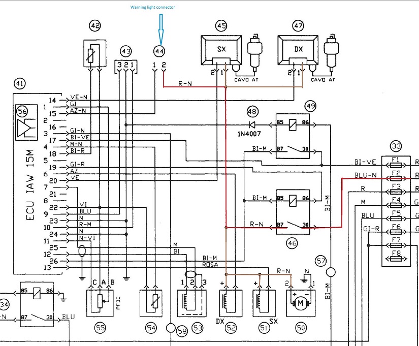
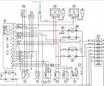
There are three different wiring diagrams and two different R/R’s in use on V11. Since yours is ’00, R/R is Ducati Energia (if not changed). Is the petcock electric or manual? If electric, the wiring is "version 1", if manual, "version 2". With this information you should get good advice from our specialist (Kiwi Roy)…
-
I studied the wiring diagrams from the workshop manuals with my non-electrician knowledge as far as I can; there seem to be three versions. With cat from 2003 on (KT), manual petcock No separate reference voltage for the (Shindengen) regulator. Only plus and minus form battery. Non cat (KR/KS) from KR 113816 on (for example 2002), manual petcock Reference voltage for the Ducati Energia regulator comes through: fuse F5 - light relay ( 34) => the circuit which is an array of many parts and contacts (high/low beam, warning lights, brake lights and horns). Non cat from 1999 on (KR), electric petcock, until KR 113816 Reference voltage for the Ducati Energia regulator comes through even one more contact; fuse F5 - start relay (23) - light relay (34) => the circuit which is an array of many parts and contacts (high/low beam, warning lights, brake lights and horns). A possible connector to get the reference voltage for the Ducati Energia regulator? On the wiring diagrams with the Ducati Energia regulator, there is a connector 44 = “warning light” which is not used, I understand (on the later version with cat, this wire leads the plus to the lambda heating). The battery plus comes to this connector from the circuit “ignition coils/injection nozzles/fuel pump". Do these draw a lot of current, what about ignition coil charging? Before these, there is only one relay contact, “injection relay” (46), the current to this contact comes directly from the F2. If the plus wire of the connector 44 can be easily found, could this be connected to the Ducati Energia as the switched reference voltage? The warning light on the dash might work after "igniton on" only during the first 2 sec fuel pump "priming" time, though (now the regulator gets reference voltage when the ignition is turned on, which stops when start button is pushed and comes back when start button is released). But it should work when the motor is running (if there is no charging).
-
OK. Thanks. Or then headlight through a relay, so that it will not strain the reference voltage circuit (as suggested earlier).
-
To change the source of the reference voltage to the Ducati regulator: there is on the starter motor always a good connection from the battery plus. This is not so far away from the Ducati regulator. Could this be a good point to connect the reference voltage wire form the regulator? A clamp under the same nut (starter)-fuse (which size?)-regulator. This would like "imitate" the connection of the later "Shidengen" regulators in a way (like it is on the later V11s, cat versions after ca. 2003).
-
I have saved this sometime from the German V11 forum.

-
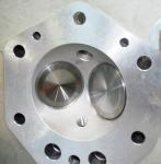
A twin spark head done by HTMoto in Germany. Don't know how much higher the CR is, but this is the thing to do if you want to change the cahracter of a V11 to a more hurried one (specially at 5000-8000 rpm).
-
I was instructed to use "wire rope" to get the vents going. Some WD40 type "wonder-liquid" in the opening, the "wire rope" attached to a light weight drilling machine. After a while the rotating "wire rope" finds its way thourgh the blockage. Complete by blowing compressed air through. Then separate hoses from the connection nipples which run to to convenient "end-locations" (no risk of getting fuel on to hot motor).
-
Could it be one of the special screws ("cuts off" when tightened) which fasten the ignition switch ?