
Lucky Phil
-
Posts
5,449 -
Joined
-
Last visited
-
Days Won
276
Content Type
Profiles
Forums
Events
Gallery
Community Map
Everything posted by Lucky Phil
-
Never thought of that, didnt realise they were dead straight. You learn all sorts of things here:) You can of course source yourself a piece of 50X20 aluminium rectangular tube and adjust it for dead straight then drill 4 holes with bolts 2 at each end that are spaced to rest on the fwd and rear edges of the rims to check the alignment. Then you can use it on any bike by just drilling extra bolt holes to suit differing wheel bases and use longer/shorter bolts for different wheel width combinations.The vertical you do with plumb bobs. The trick is knowing how much misalignment is production based. Ciao
-
True but as with all things its the details that make or break. So some of the issues in that regard are pump dimensions, pump mounting requirements, outlet and inlet sizes compared to the tank, pump inlet and outlet orientation, etc,etc. it always looks easy on paper but can turn into a head @#!#$# when it comes time to actually do the install. Then if you do have a running issue initially you are always wondering whether you failed to consider something with the new hybrid system and you start digging yourself a hole. My bike is an example, seems simple sourcing a new/replacement fuel filter to fit but believe me it took a lot of research mainly because of the space requirements and i still took and educated guess on the filtering requirements. Ciao
-
Some of the later injection systems are a variable pressure arrangement that vary the speed of the pump via the ecu as a primary control of pressure and therefore dont require a return circuit and regulator but you could in principle use any pressure source and reg you like,BUT take it from me after years of experience with these sort of things its wise where possible to not mix and match components from different manufacturers and systems to this extent. If you use the later V11 system you take out a whole lot of possible variables on a whole lot of levels and when and if you run into an issue at least you know you are dealing with a system that is proven to work on your specific installation. A large access hole is an advantage not a disadvantage foe maintenance and possible repairs. If you want the cheapest possible solution then go with an external pump,reg and filter for sure. Just 2 simple and cheap spigots to incorporate into the tank. Ciao
-
True docc but that relies on the vented fuel having an escape route and in the case of a V11 that route is the tank cap recess drain. Ciao
-
I would forget the keyed cap and use a nice race cap. I have one on my bike. You can even buy race style caps these days with a dedicated small tool key that you keep on your key ring if you worry about people stealing fuel or such things. https://www.ebay.com.au/itm/Fuel-Filler-Cover-Gas-Tank-Cap-w-Key-For-Suzuki-GSXR-1000-600-GSXR750-Hayabusa/264583557906?hash=item3d9a68b312:g:2rgAAOSw3fFeCcxK Ciao
-
The best solution if you are going to make a tank from scratch is to use the pump/filter/regulator and mount plate assy from one of the later v11's with the in tank pump. This keeps the regulated pressure standard and tidies up the fuel hoses around the engine. using a pump and reg assy from a Japanese bike seriously complicates matters. As for venting and cap, well there are a gazillion different aftermarket cap solutions out there quite cheap, take your pick. Same for the venting. The simplest solution is a small fitting on the front of the tank with an in line check valve to a small remote catch tank ( I used to use old small plastic pill bottles) or dump to the ground such as we used to run on race bikes a few years ago. Once again a million affordable options out there. Ciao
-
Corona / Covid19
Lucky Phil replied to Admin Jaap's topic in Special place for banter and conversation
Don't stress NZ doesn't have the same issues as Italy in that it has the worlds 2nd oldest average population compounded by the fact that they also have a very high level of contact with the younger members of their family's which tend to be less/minimally affected but transfer the virus to their elders. The panic buying here is just nuts. I totally refuse to get involved with that moronic behaviour. Ciao -
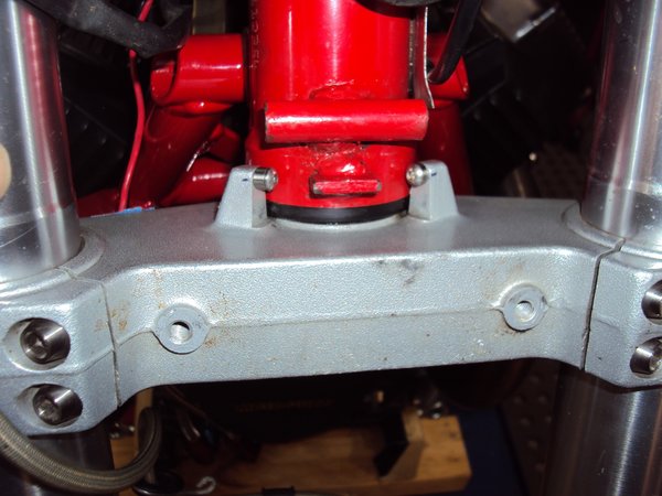
So onto the steering stops. My preferred option was to machine off the original lower triple clamp stops and make new adjustable bolt on ones but I simply dont have access to the equipment required these days so I thought long and hard and decided on plan B for the time being at least. I tapped and drilled a hole in each stop and machines up some Ti spacers combined with button head caps. Drilling and tapping accurately the stops in situ was interesting to say the least but I surprised myself and got it right for a change. I made up a rather crude tiny 5mm thick alloy plate with an accurate hole through it to be my guide and clamped it to the face of each stop and used my die grinder with a drill chucked up to drill the holes as there was limited room for a hand drill. Used the same process to get the tap aligned for the tapping process as well. Next job is the top triple clamp off to freshen up the paint where the previous owner used to ride with a key fob flapping about damaging the paint work. Why the hell people ride with key fobs flapping around is beyond me. I've never used such a thing in 50 years of riding. Ciao
-
From the album: V10 Engine
-
Yes, I do believe so. Ciao
-
^Just the nature of the design. Ciao
-
Yep aluminium, you guys take way better images than me thats for sure but when I checked both my engines(one with and one without) thats the view I got of the ally unit and Chucks images also show the differences clearly. You can also slide a 6" steel rule into the hole and measure to the edge of the hole and see the differences in the depth as well but you need to be precise about where you take the measurements. Ciao
-
Its fairly easy to tell through the inspection plug if you know what to look for. I tried getting images of my new engine with the single plate clutch and the old twin plater but couldnt get anything meaningful with the camera through the hole. Ciao
-
Yes and you negate the lifting ramps on the cams which gives the followers and retainers a hard life. Ciao
-
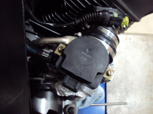
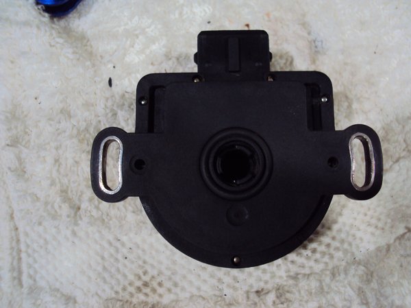
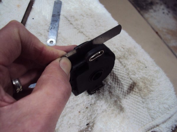
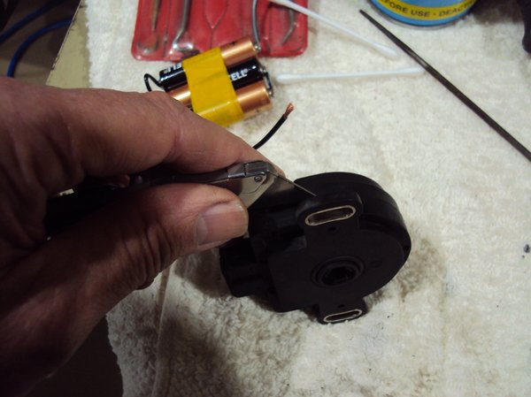
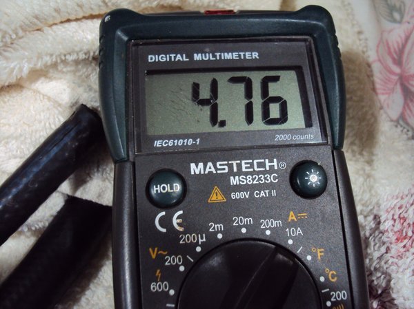
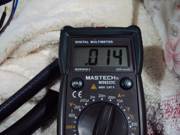
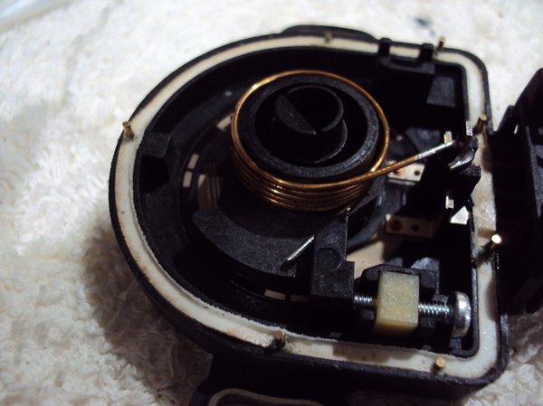
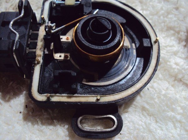
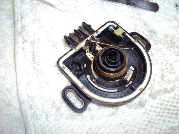
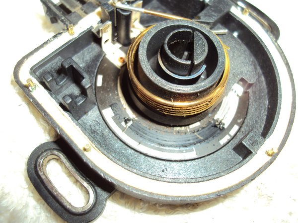
So I thought I'd have a play around with the throttle bodies and TPS sensor and also confirm my wiring for the PF09 TPS was correct when fitting the old style plug to the V11 loom as the colour coding is different. I made up a 5V power supply and some flying leads and confirmed the TPS read outs were correct and thought i'd do a preliminary set of the TPS which I can confirm when I power up the system on the ecu. bearing in mind that I have no idea how this engine ran or the mileage originally the TPS condition could be anything and I want to eliminate as many variables as possible. mechanically the Throttle bodies are acceptable from a wear perspective although I replaced the plastic connector rod ball assembly. Unfortunately I couldnt get the TPS reading below around 200MV unless I tapped it with a screw drive handle and then I could get it to around 140MV with the throttle blade completely closed which would work if evertime you stopped you tapped the TPS. I ran out of TPS adjustment so I decided to see if I could pull it apart and see what was happening. Although this isnt really relevant to the V11 as it uses the later TPS it might be to anyone following in my footsteps down the track. The PF09 TPS is held together with small metal press rivets so I used a box cutter blade into the joining line and gently twisted the blade to get the rivets to release. Going from one side to the other slowly slowly until I could get a 0.020" feeler gauge length ways into the gap and use those. It helps if you use one on each side simultaneously to prevent the halves rocking as it separates. The whole process took quite a while like 15 minutes but it came apart without looking like it had been apart, ie not butchered. This is the process. And this is what it looks like apart. Note the crud and rubbish on the wiper fingers and also the foam seal and rivets. Also note the strong return spring and wiper faces. Here it is again after cleaning with a very small paint brush and contact cleaner followed by contact cleaner and cotton wool buds. Here you can see the closed stop screw assembly. So after cleaning I hooked it up to my 5V supply and checked the operation. Still not able to get it below 190MV but it was stable now. So next step was to adjust the stop screw. Nothing magic here just adjusted it until the reading bottomed out at 14MV and left it there. Not sure why this was the way it was, dont think wear was a factor, maybe it wasnt adjusted properly from the factory. Dont really know. , Wide open throttle, 4.76 volts which is the nominal voltage of my power supply. Anyway re assembly is simple just put the halves together and use a small tool to press the securing rivets back in place.I also changed the securing screws over to the Torx type I had off another set of Ducati throttle bodies as my original straight slot fasteners were a bit ropy. Ciao
-
From the album: V10 Engine
-
From the album: V10 Engine
-
From the album: V10 Engine
-
From the album: V10 Engine
-
From the album: V10 Engine
-
From the album: V10 Engine
-
From the album: V10 Engine
-
From the album: V10 Engine
-
From the album: V10 Engine
-
From the album: V10 Engine


