
Lucky Phil
-
Posts
5,449 -
Joined
-
Last visited
-
Days Won
276
Content Type
Profiles
Forums
Events
Gallery
Community Map
Everything posted by Lucky Phil
-
From the album: lucky phils V11
-
From the album: lucky phils V11
-
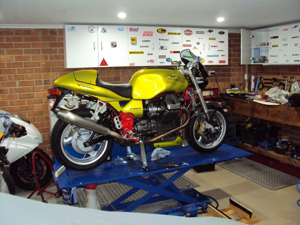
My attention was drawn in that image to the wall art of "Prince" from the movie Purple Rain. Anyone that thought he was stylish or cool had their bubble burst when he appeared riding that atrocious abomination of a motorcycle. All the cool and style instantly evaporated, like gasoline spilled on a hot engine and he is revealed for what he was, a scrawny, weird little dude in high heals. If you want to know how cool someone really is ask them what sort of motorcycle they own or aspire to own. PS great song writer though. Ciao
-
Ticked another couple of boxes today,added gearbox oil and reworked the seat. I found with the tank raised and in a rearward most position dictated by the aft mount slot that the seat unit wouldn't latch down. Turns out I needed to trim 10mm from the front of the seat base so I removed the staples that secure the front of the cover and removed 10mm from the ctr tapering to zero about 50mm from the corner. Re-stapled the cover back into place and were're golden. I also shimmed the seat latch up a few mm so it latches nicely now. It always required a bit of a shove down to latch properly but its quite nice now. Seem to be getting close to the finish line now, refit the tail under tray and rear plate holder and machine up the final tank rear mount spacer and fit the oil pressure gauge for the initial start. I'll wait a little for that and collect my thoughts and go through a check list of double checking stuff. Ciao
-
Ha, sounds like a wise move docc. I re-checked the spare nylon covers I have on my spare really nice late model airbox and with all the grommets and spacers fitted you cant mount the cover without significant distortion to the cover which is what eventually causes them to crack it appears. One mount hole on each cover is a long way out. Once that is corrected then they fit up with zero load. Might be a project for the future,fibreglass covers with the holes in the right spots. Good to know the carbon ones dont seem to be an issue,although they are very difficult to find. I machined 1 mm off the tops of my new cover screws and they look a bit better now. Ciao
-
Is that the carbon ones Chuck? Yes engine cowls can be a challenge even hinged ones on high bypass jet engines. Light a/c ones are just a misshapen pile or wobbly tin foil until latched into place I would imagine:) Ciao
-
45-50NM Ciao
-
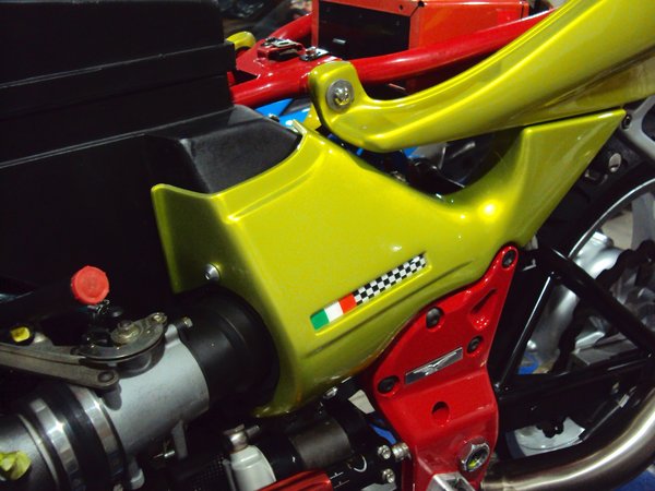
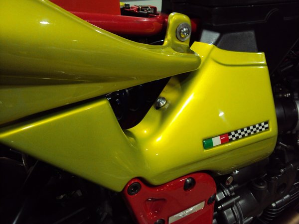
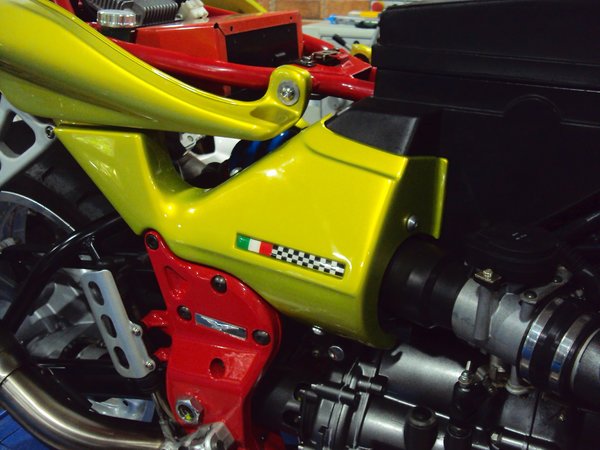
Some time today was spent resolving the side cover fitment. Since day 1 owning a V11 the fitment was rubbish which caused cracking around the mounts. Eventualy my LH cover front mount area lost a whole piece the crack extended so far. I dont know if this is typical( I suspect it is as I have 3 sets of covers and a spare airbox and the fitment seems the same) The RH cover here is a brand new factory unit and the LH is a freshly painted repaired one, both bought years ago awaiting their time in the sun so I'm keen that they dont crack. I'd be interested to know if the factory carbon covers fit any better because the Nylon originals are appalling. The only way around the problem that I could see was to elongate some of the mounting holes so the covers could fit without any loading at all. I achieved this and to assist with future longevity I machined up the heads of some aluminium 5mm button head screws I had laying around. I must say I'm not enthralled with the looks of the screws as i'd rather something small and discrete like the originals but I wanted some fixing area around the screw heads. I machined the buttons down from 16 to 14 mm head dia and took the roundness off. Like I said a bit too chunky but there you go. First image and this is whats required to make the LHS cover fit without any load on the mount points. Elongate the top hole 7mm. I mean this hole is nowhere near the right location. The LH cover didnt need any rework to this mount but required around 5mm elongation to the lower hole. Ciao
-
From the album: lucky phils V11
-
From the album: lucky phils V11
-
From the album: lucky phils V11
-
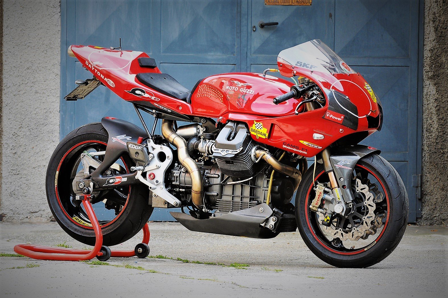
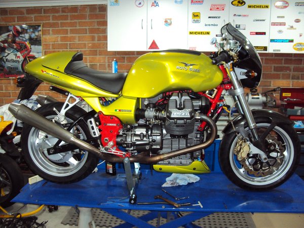
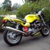
Yes I'm happy with the way it looks. Raising the tank seems not to have had a negative impact. I might leave the rack off, initially anyway as my wife cant get pillion for the moment. I only had it fitted as a really good pillion hand hold. Its a great looking engine that's for sure, a look that engenders a feeling that danger may exist here. Bit like a big radial aircraft engine. When you know whats thrashing around inside one of those thing its a little bit worrying and scary. Ciao
-
From the album: lucky phils V11
-
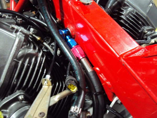
So I decided to defer the tuning fuel tank job, just a bad time to do it really when you need to ship stuff and fitted up the fuel tank instead to do a leak check. Popped the injector connectors off and did repeated pump primes to pressurise the system and fill the lines. All good except for an externally leaking fuel tap when in the open position. These thing really are a POS. My original one jammed in the open position and this one inexplicably decides to leak from the shaft seal when open. Anyway I got my old one that had jammed open which I had after that event reworked somehow and fitted that. Hopefully it wont repeat the same defect. I then moved on to fitting the airbox so I could attack the side covers. The side cover fitment really is horrible on these bikes as they eventually crack due to the poor fitment strain. Need to have a think about solving this as I have 1 brand new cover to fit and one reworked one and I dont want them cracking. Couldn't resist fitting the tank and tailpiec to get an idea what its going to look like. Ciao
-
From the album: lucky phils V11
-
From the album: lucky phils V11
-
Make fuel checks easier:) Ciao
-
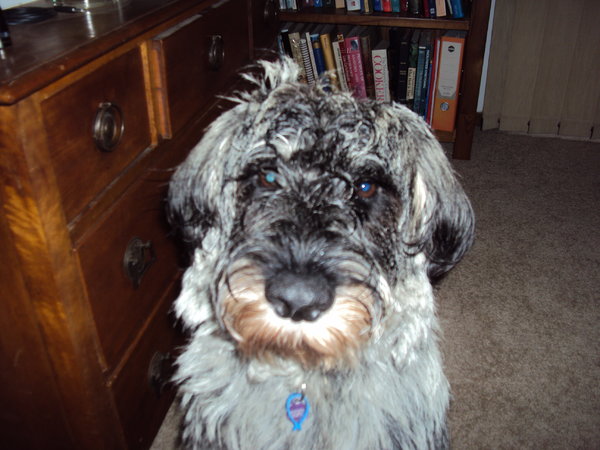
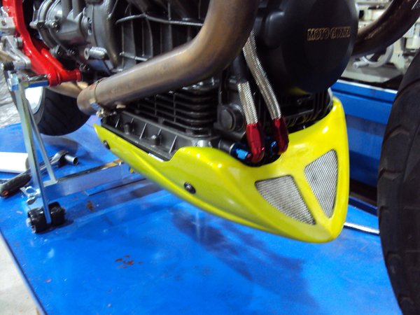
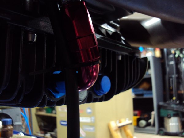
Yes docc just for you A few other jobs ticked off today. Got my lower spoiler installed and made up the oil return line. Next job is to make up a remote fuel tank for tuning work. Merlin doesn't care about viruses, he's just happy his mummy and daddy are home 24/7 Ciao
-
From the album: lucky phils V11
-
From the album: lucky phils V11
-
From the album: lucky phils V11
-
From the album: lucky phils V11
-
 Cant seem to play any video posts lately,even the ones I've previously posted.........must be the corona virus. Ciao
 -
Correct, with a spongy feel. Lots of lever movement with little slave travel. Different to a rock solid lever that wont move at all. Ciao
-
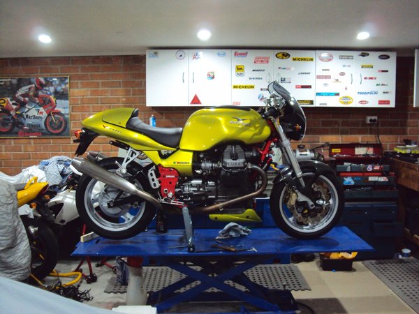
So some progress. I've managed to get the front end back together and finish off the wiring. I painted the top triple clamp and gave everything a good clean up while I was there. I bought myself a stand which I should have done years ago as the one I have was a home made job from the previous owner and very dodgy and dangerous to use. I'm carrying too many old injuries these days to struggle with the physical stuff, when there are sensible options,so I dont. On its wheels. The braided breather hose is the next job to finish off. The Throttle bodies and TPS are set up but I need to source a fuel canister to make a tuning fuel supply so I can remove the tank and bench it and hook up a small fuel supply. After reworking the TPS and getting that working I bit the bullet and decided to buy a good second hand set of Ducati throttle bodies. So for about 130usd I ended up with a pair of near new side flow injectors,a TPS, a fuel regulator and mounting assembly I'll use on the remote fuel tank, plus a bunch of spare TB parts inc the pivot ball and some spare plastic fuel fittings that are worth around $45usd ea to replace with alloy aftermarket ones if you break one of the originals. I've now also got a single throttle body that I can use to clean side flow injectors which turned out to be quite an issue finding someone to do. Wiring Repainted top triple clamp Stand....German made! Ciao


