
Lucky Phil
-
Posts
5,449 -
Joined
-
Last visited
-
Days Won
276
Content Type
Profiles
Forums
Events
Gallery
Community Map
Everything posted by Lucky Phil
-
What Ducati? I bought a factory alloy tank for my 1198. Ciao
-
The only genuine solution docc is an alloy tank. You could of course have a spare tank and periodically rotate them on the bike so the one not in use is dedicated to drying out. Then swap them around and dry out the other, or coat the tank. Ciao
-
Now you know why when I designed my new front tank mount for the V11/V10 project I made the mount adjustable up/dn and fwd/back. You cant remove any material off the dia or the tank will be loose up and down. Only off the rear of the puck. Ciao
-
The usual basic method is to immerse the part in a warm Loctite 290 bath for an hour or so then remove and rinse off. A friend of mine had his E type Jag engine professionally rebuilt a few years back and the engine guy did this with the brand new sump even before it had been fitted due to history of leaks. If you clean a head or crankcase down thoroughly and put it in an oven at 100 deg C any porosity will usually show up with a very careful detailed look or you can buy a Dye check kit and spray the cases with a light coat of the developer only after a thorough cleaning and drying and that will show it up as well. warmed in the oven even better. Any oil in the porosity will be very obvious as it was on my head images. Dye check kits are cheap, probably around $20 us over there and I've used mine more times than I can remember over the years. Ciao
-
Yes there's quite a few processers that can be used. The Loctite 290 is basically a low viscosity resin as well. It's obviously best to get full penetration but anything that seals the porosity is fine. Hence external painting by the factories. Ciao
-
Sorry, with the plate installed and before you fit the sump insert the dipstick and mark it level with the plate lower surface then remove the stick and drill a hole. This way you know exactly when the oil level is at the bottom of the plate which is full. Ciao
-
Nice video. A good thing to do once you have the plate installed is to drop the dipstick in the hole and mark it level with the bottom face of the Roper plate, remove and drill a 1.5mm hole in the dipstick as your new "full" mark. Ciao
-
Yes Pete "super wick-in" is the 290 green stuff. Low viscosity. And yes Araldite is another fix. Many round case bevel drive Ducati's back in the early 70's had Araldite in the cases from the factory. When I put Desmoquatro engines together with new cases I used to go to the importers and they would bring out their whole stock of crankcases and I'd go through them and chose the one with the least porosity. Not, no porosity but the least! Ciao
-
How About Some Pics from The Roads Down Under
Lucky Phil replied to Kane's topic in Travel & dealers
He was, I'm not sure the gearbox was though Ciao -
From the album: V10 Engine
-
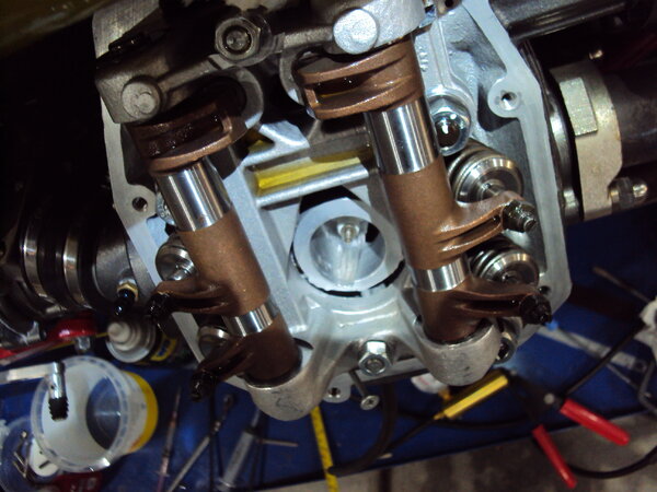
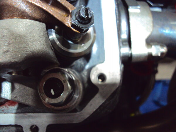
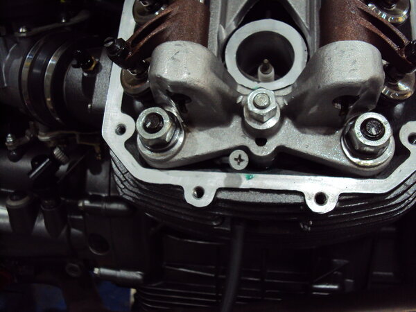
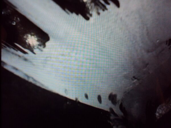
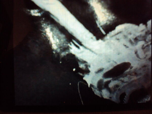
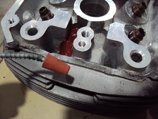
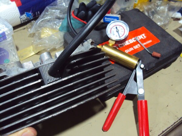
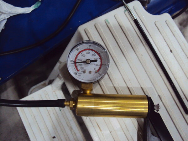
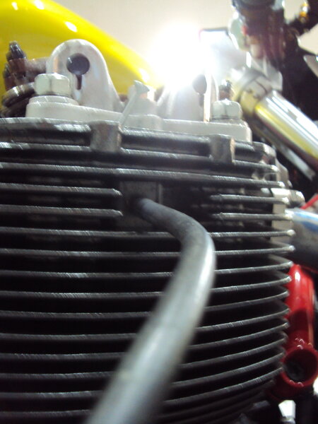
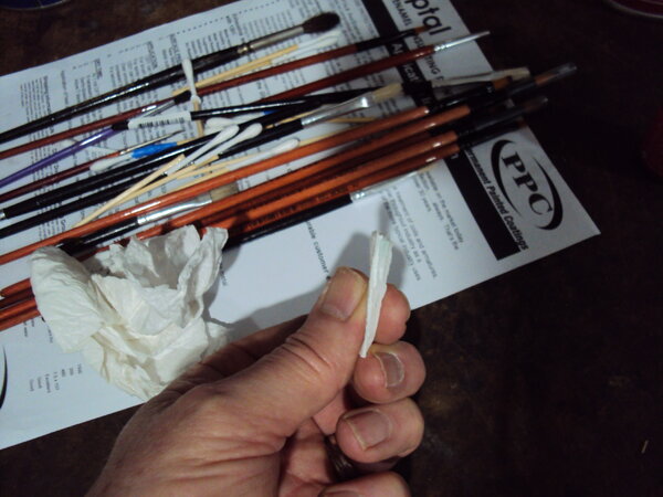
I've experienced casting porosity quite a few times over the years with Italian motorcycles so why would the V11/V10 be any different. I thought I'd do a piece on dealing with it in the case of the Daytona engine, specifically the cylinder head. It's of course of no real import to anyone here V11 wise but may be of general interest. My original V11 engine had an issue with the oil drain back gallery in the l/h head apparently which the original owner had rectified with a sleeve. I've not had the opportunity to look at it but it has never leaked in the 10 years I've owned the bike, so I'll call it fixed. The issue with the Daytona engine arose a few months after I got it running with an annoying accumulation of a small amount of oil on one of the r/h cylinder fins. Originally I put it down to a leaky rocker cover gasket but a careful evaluation found it to be from one of the rocker cover attach screw blind holes. Four of the cover retaining screws are on the "wet" side of the cover o-ring and are blind holes to the external part of the head. Several of these holes had been over drilled at the factory by a very small amount and broken through to the head exterior. Oil was seeping down the thread holes and working its way to the outside and eventually to the edge of the cooling fins. Great, simple fix. Either seal the screws on fitment of the rocker cover, which is a bit of a pain or somehow seal the bottom of the holes. I took the latter path and screwed a 6X4 grub screw down to the bottom of the holes sealed with Loctite 242. This still left me with 12mm of thread engagement which was plenty. Here's a totally inadequate image of the screw hole with the grub screw in the bottom. Unfortunately the leaks persisted. I suspected it may have been from the spark plug drain gallery vertical wall. The vertical walls of this area of the head form an internal pair of drain "wells" with the head drain galleries at the bottom of these rectangular wells. Measuring a spare head I calculated the wall thickness here to be around 3mm which is pretty thin for a sand casting. I also recalled a brief thought flash through my mind when I was painting the heads that I'd better get paint up in there or I might end up with an oil seep issue. Funny the fleeting thoughts that come back to you in hindsight. I've long suspected that one of the primary reasons for the Italians painting engines going back 35 years of so was to preclude these porosity issues. Here you can see in this damaged spare head the drain wells and the spark plug drain gallery exit between the fins. One well has a red sealing coat over the area that forms the roof and vertical wall of half the plug drain gallery and the other roof section and vertical wall section is unsealed. I wanted to test the sealer in the oven to makes sure it would stand the local heat in the head. I painted on some dye check developer to these vertical walls inside the plug drain gallery and sure enough the tell-tale signs of porosity seeping. First image the r/h head and the second the l/h. The dark round patches in the white developer are the tells. So the challenge is how to fix this without pulling the heads if possible. Pulling the heads is a pain. Apart from the actual work involved you then need to go through the retorque process and reset the valve clearances etc. painful. Part of what I did in my professional aviation career was to come up with insitu technical solutions to to keep aircraft out of the hangar flying an earning a dollar so I put that hat on and had a muse. The typical way to address porosity issues is to clean the component, heat it up which will usually bring any trapped oil out of the casting and then drop the whole thing in a warm bath of loctite 290 wicking grade and let it soak for a few hours and wash it down and the porosity is sealed. Not possible here of course without pulling and disassembling the heads. There are commercial variations on this process that immerse the component in a vacuum chamber and then a pressure chamber of 290 or variations on that material but once again not insitu. What I eventually came up with was a vacuum system using a brake bleeding pump and home made rubber seal. I sealed off the spark plug end of the plug drain gallery with aluminium tape and connected my homemade seal to the vacuum pump at the outer end to create a 27 inch vacuum in the plug drain gallery. The outer rubber seal was made from an old piece of rubber thong sole. This would hold a vacuum quite well with a few pumps every 3 or 4 minutes. An image of the aluminium tape used to seal the plug drain gallery at the plug hole end I then devised a rubber plug to seal the drain hole in the bottom of the head drain wells. A little tricky as with the head rocker gear support installed the hole isn't visible without a mirror. Here's the plug. Here's the plug installed on the head on the engine with the drain well filled with 290. Some of the images are from "proof of concept" experiments with my spare damaged head on the bench. Painting on the internal sealer insitu was a fiddly job with the rocker arm supports in the way but with small brushes bent to various shapes quite doable. So the process now was to fill the plugged drain well and fill them with solvent and pull a vacuum in the plug drain gallery to draw the solvent through the porosity and clean out residual oil. Then dry out the drain well and repeat the process with the loctite to seal the porosity. I inserted a small piece of paper towel inside the plug drain cavity on both occasions with the solvent and the loctite to get an indication if my process was sound. If you look carefully you can see a light green tinge to the paper, so the solvent and loctite were migrating through the porosity. So repeat for the other head area and the jobs almost done. I wanted a little "belt and braces" assurance so in addition to the loctite sealing I also coated the well areas with Glyptal internal engine sealer as well. That's the reddish coating. So I can claim a complete success I'm happy to say. Nice and oil tight. Next time I'll listen to my small internal voice a bit more closely and do the due diligence on those areas I know intuitively could be an issue. Ciao
-
From the album: V10 Engine
-
From the album: V10 Engine
-
From the album: V10 Engine
-
From the album: V10 Engine
-
From the album: V10 Engine
-
From the album: V10 Engine
-
From the album: V10 Engine
-
From the album: V10 Engine
-
From the album: V10 Engine
-
Here's some interesting information from Beard ( who invented Guzzidiag) on the German Guzzi site with regards to map applicability between different 15M ECU's. http://www.guzzi-forum.de/Forum/index.php?topic=50506.0 From 15M to 15RC goes.From 15RC to 15M does not work.In PC jargon:You cannot copy a (full) 8GB USB stick to a 1GB stick.The other way round is not a problem.The comparison lags slightly, since the same IC with 64kB FLASH is built into the ECUs.But the 'BIOS' of the 15M only erases and writes 32kB,the BIOS of the 15RC erases and writes 48kB. Ciao
-
Really, you haven't spent much time in motorcycle repair shops obviously. Do you think the fool riding his bike around in shorts, singlet and thongs has any better idea of mechanical maintenance than safety awareness? Some of the mechanical sights I have seen. Ciao
-
How About Some Pics from The Roads Down Under
Lucky Phil replied to Kane's topic in Travel & dealers
I'd love to hear his commentary if he rode something that actually made genuine power. Sounds like it needs the mapping sorting between 3-4k from the commentary. The V11 needs a technique to shift cleanly even without the extended shift arm. Ciao -
A new OEM oil drain plug crush washer design?
Lucky Phil replied to Kane's topic in Technical Topics
Show off. No make that "cheap" show off Ciao -
No docc, bigger is better with me. I don't want no stinkin, skinny arsed 4.5" rear wheel:) Ciao


