Scud
-
Posts
4,123 -
Joined
-
Last visited
-
Days Won
253
Content Type
Profiles
Forums
Events
Gallery
Community Map
Everything posted by Scud
-
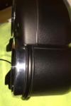
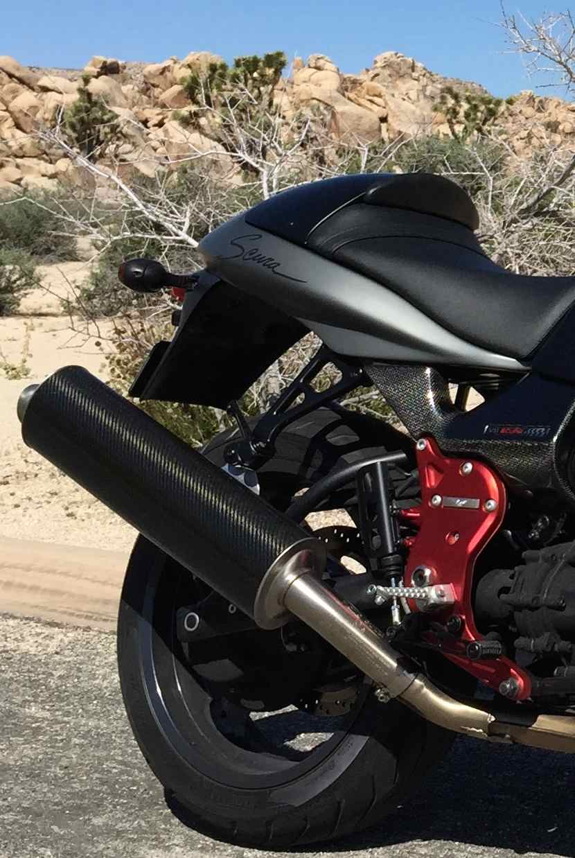
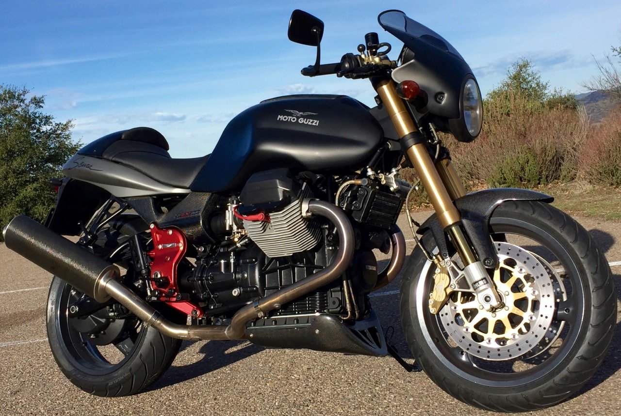
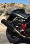
Thanks guys, the bike cleaned up even better than I hoped, although the paint is not perfect. Here’s another gratuitous photo – cuz what’s better than looking at pictures of bikes? http://i1128.photobucket.com/albums/m492/timscudder/v11com%20misc%20photos%20posted/LeMans%20Project/IMG_3157.jpg From this angle, you can see how the Ti pipes tuck in. I really like the shape and position of these. I was impressed when he told me he cut them down. That does seem like a tricky job, not one I’d feel comfortable doing. The LH side has some, let’s say, “bonus rivets” when compared to the RH; these contribute “character” to the bike. I don't miss the front crossover exhaust pipe or the winglets on the fairing, nor do I miss the bright orange turn signals lenses, which are morally wrong on red motorcycles. From this angle you can see almost everything else I’ve been thinking about powder coating. A deep bronze, very close to the color of the Moto Guzzi logo on the tank, is available. I’ve been thinking to do: wheels (which have some chips and scratches), alternator cover, valve covers, plug guards, porkchops, and fuel door that color. But darkness is also beckoning and I like the one with the black porkchops in the gallery that I referenced earlier. So maybe everything should go flat black, which is the same as the first batch of powdercoating and the exhaust hangers, passenger pegs, and rear brake master cylinder guard which you can (barely) see in this photo. Is anybody happy with an aftermarket fairing mount mirror? Ideally something that looks a bit lighter and does not have a rubber boot?
-
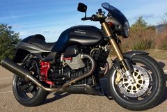
I got a little package of parts delivered yesterday, so was able to get it on the road this weekend. Here's the rest of the sorting out: Retorqued heads along with new valve cover gaskets and O-rings. (had to remove PO's adhesive from one cover... tedious...) Adjusted valves to .006" Intake and .008" Exhaust. Set suspension sag. Went through the TPS and throttle body synch procedure. The TPS breakout harness is really handy - and I got to test my homemade manometer for the first time. Installed clutch and brake switches. Elongated holes in side covers to get them to line up and not rub the tank. Re-glued heat shield under tank Changed transmission and final drive oil - used the Redline Shockproof gear oil. Dang, that stuff is crazy... it was still clinging to the funnel after sitting overnight. Final (I hope) fussing with wire, hose, and cable routing. Took it for a 100-mile shakedown. Here she is in her natural habitat - and returned pretty close to stock. Ride report: Oh man, I love these bikes... (preaching to the choir, right?) It runs sweet and strong. I don't know how much power the Kit Racing ECU and exhaust add, but the sound is rumbly and glorious and makes me think it's faster. Hard to say which changes were most important, but I think getting the small pods off, replacing the stock airbox and putting the sensors back in the right places was probably most important - then the general tune-up stuff. I did notice a few very minor hiccups at idle after running hard, so I think I will go through the TPS and balance procedure once more - making sure it is at full operating temperature this time... like the instructions say... Originally, I was disappointed that the PO cut the Titanium cans down (a few inches shorter), but they're really growing on me, despite the fact that they are a little ratty. As for handling, let's just say I would have been absolutely thrilled if I had never felt the Ohlins. However, I think the Sachs shock is not in good shape - maybe it was crap to begin with, but the fact that it ran for a while with a much shorter spring probably didn't help. So I think I am in the market for a replacement shock. I didn't even think about the Shindy steering damper - so that must mean it's working well. It also needs a front tire. Gauges all working now (but pending new oil pressure sender that will let the gauge start at 0). It's nice to have the volt and oil gauges instead of the warning lights - after reading so much on here about oil pressure and charging issues, the gauges give peace of mind. I now believe that my earlier oil light concern was due to a faulty sensor. So, let's call this Phase One and ride it for a little while.
-
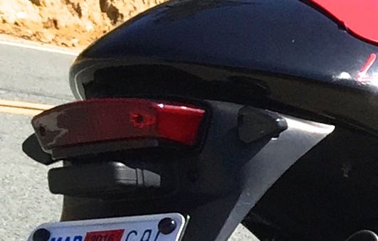
Here's a little thing I'm pleased with (and this one's cheap). $10 for a pair of these smoked LED turn signals. They fit really well on the stock fender and are much brighter than the stock signals. I could not get them to fit on the fairing, which was my original plan. Of the four stock signals I had, only two were nice enough to put back on. I originally had the stock (and tinted) signals on the back but moved them to the front. Did you know that you can run LEDs in the back and incandescent up front without changing the flasher unit? I didn't know that, but all four signals are working... lucky me.

-
I have never done this job on a Moto Guzzi. I was only comparing to a similar experience on my Husky, because replacing just the O-ring was a waste of time on that bike - and the time investment on the Moto Guzzi looks to be much higher. If riding season is truly over for a while, I would take it all apart like SteveS suggested and give everything else a proper clean, inspection, and service at the same time. Maybe someone who's actually done it can help. I just took a look as though I were trying to remove the slave cylinder. I can get a 4mm allen wrench on two of the three screw heads, but access to the third is blocked by the frame. So - I don't see how it comes out without removing the swingarm and the lower frame. At this point, if it was me, I'd call a MG dealer or parts supply and try to get some free advice along with my parts purchase. Or maybe this is one of those jobs that's worth paying someone else to do.
-
Here's a link to the same picture as Docc posted, but with part numbers and prices: http://www.harpermoto.com/parts-by-motorcycle/2000-up-moto-guzzi-motorcycles/v-11-cat-1100-2003-2004/clutch-en-v11-cat-1100-2003-2004.html I was curious about the difference in bolt patterns that you mentioned. So I just looked at both of mine and they are the same as you describe. It looks like there is an extra hole on the case. Therefore, I assume that Moto Guzzi used various clutch slave cylinders over the years on the same cases. It seems to me that replacing the entire slave cylinder is most likely to solve your problem for the long term. When I had the same problem on a different bike (as mentioned in your "case of..." thread) the rebuild only lasted a short time. Then I put a whole new slave in and it lasted till I sold the bike recently.
-
The reservoirs and brackets are by Rizoma. I found them at a discounted price with free shipping at http://www.motovationusa.com/mvstore/scripts/prodList.asp Tanks come in many sizes/shapes/colors. I got part number CT025 in black. There are several bracket options, the one for Brembo master cylinders are part number CT450. FWIW - I used the same size reservoirs (that they call "tanks") and brackets for clutch and brake, because I like the symmetry. Tanks are a little bigger capacity than the stock clutch tank and a little smaller than the stock brake tank. I put the same on my Scura a few months ago (working fine) and the guys at my local dealer said there is no problem running a little smaller capacity on the brake cylinder for street use so long as you check/change the fluid at regular intervals.
-
Thanks - I think I will try that experiment at the next opportunity. Meanwhile - I'm back to brake cleaner. I only used WD-40 once, based a friend's advice. He'll be interested in the experiment too.
-
Ha - you're the only one that responded in 13 years. My bike hadn't even been made when that was written. Funny though - that sounds exactly like what's MG did with the Kit Racing Titanium exhaust (cans, ECU, and hangers.) My Kit Racing exhaust cans are turned way up and in. I do like the look a lot. I'm not having any problems with ground clearance though... anybody want to buy a set of used tires with lots of tread left on the edges?
-
Thanks for the input - I've still got some time before I put it on the road. Meanwhile I did some additional research/reading. Here's what I found: Lots of people swear by WD-40 as a brake caliper cleaner (so long as it is not left to sit or allowed to contact the pads) and say they've used it for many years with no ill effects on bikes and cars. Lots of people warn that WD-40 is among the worst things you could ever do to your brake calipers. WD-40 does not divulge their secret formula, although they disclaim that there is no fish-oil in the recipe. Apparently some people think that spraying hooks or bait with WD-40 helps catch fish... can you imagine the conversations at the fishing-forums (if there is such a thing)? But WD-40 is a solvent and Water-Disbursement agent more than it is a lubricant. Lots of people advise for using brake cleaner. Nobody advises against using brake cleaner. If I had some spare brake components around I would happily conduct an experiment - although I think I will stay away from the WD-40 now. It seems like brake cleaner is the safe way to go and I think I will take 'em off and give 'em one more cleaning, maybe get the pistons moving even more freely. A couple other questions, since we're talking brakes (and I have recently read too much): Do you use any type of lubricant around the pistons after cleaning the calipers? In past, I have just used brake cleaner and no lube. How often are the calipers likely to need rebuilding? Kits are cheap and that's one way to make sure everything is in good order.
-
Glad you were able to enjoy it for a while longer and wait for off-season to repair. There's an exploded diagram on the previous page of this topic (post #4).
-
I'd like the logo for possible future use and sent you a PM. Isn't it also possible to post them right in this thread as an attachment that people can download?
-
Yeah - so much customization that you can get about whatever you want - and everyone can satisfy their personal preferences. The thing I learned yesterday is that they don't even stop there... they can rebuild the gauges inexpensively and let you change options at that time. With all the extra lights on Chamberlin's you could almost eliminate the warning lights - especially if you had somewhere to put oil and volt gauges. I, too, thought "I wish I had got the remote buttons." The black buttons stand out too much against the white faces. So, if you're inclined to pay $20 per gauge for a rebuild, you can change all your options at that time. New face was another $10 per gauge. I didn't inquire about the cost of remote buttons (which would require new glass). I expect I will use the mileage reset button frequently, to reset the trip meter after refueling, and I'm sure that could be located somewhere accessible, but out of sight. But as you noted, you only have to use the speedo button once - you could probably locate that very remotely (in a box) after using it once.
-
Welcome. I sometimes miss some of my ex-bikes, but I have never missed my Honda Superhawk 996. Is that what you had? or was it the 1960s 305 Superhawk? I just replaced my front brake switch this week. It came with connectors in a different place than the original one, so I needed to snip those and do some soldering, but it works fine. The new one also seems more durable than the one that failed, so the extra effort was OK by me. Watch out for tiny parts...
-
I put the LeMans back together enough to start it and ride around the block. Mostly spurred by a concern about the oil pressure sender. Oil Gauge: When I connected the oil pressure gauge signal wire to the signal terminal and turned the key on, the gauge registered 25psi. So I thought - "Wow, That's Fantastic (aka WTF?), I've got oil pressure and the bike's not even running." I contacted Speedhut, and apparently this sender sometimes doesn't get set correctly at the factory. They offered to send me a new one if it didn't test out. The good news is that the pressure increased a lot with the bike running, but it did not settle back to 0; it still went to 25psi, and this is not because of the stepper motor, it always goes to 25. Therefore, new sender unit is needed. I also learned that Speedhut can (for about $80 extra) convert the gauge to their next level up, which is somehow better, but looks the same, and also uses a smaller sender unit. I'll pass for now and see if I can get their entry-level gauge working correctly. Voltmeter: Seems to be working well. Registers a bit under 12 with key on, and increases as expected with the engine running, and a bit more at higher revs. Speedo: Works fine with the GPS sensor underneath the fairing and at a pretty steep angle (between oil and volt gauges, stuck to inner dash panel with foam adhesive tape). Tach: Also works - but needs to be calibrated for a 2-cylinder engine pulse. I think it's reading half-speed as though it's measuring a 4-cylinder engine. FYI - Speedhut can put new faces in their gauges for $30 each if you send them in. So if you want a different color, logo, etc., it's easy to do.
-
Happy handlebar day. Gauges functioning and almost all set (details in the Speedhut gauge thread referenced earlier). New fluid tanks, powdercoated dash, blackened screw heads, had to remove the brake line at the master cylinder to properly reinstall the rubber grommet where the line passes through the under-fairing. A lot of things had been routed awkwardly for the PO's high bars. See "before" picture of bars/dash in first post of this thread. In other news - I just put it back together enough to ride it around the block and make sure everything I've done so far was working (and mostly to test the oil pressure sender and gauge). It's coming back apart again for: looser valve adjustments and valve cover gaskets, new throttle cable (I noticed a kink at the throttle body and frayed strand, due to the stress on the cable from awkward routing)... and the list goes on... I think I am about done fussing with electric stuff and wire and hose re-routing. Although I just noticed that I need to re-route the line from the rear master cylinder to the reservoir, which was also routed awkwardly to accommodate the lower and more forward footpegs. Just glad it fired up with everything re-attached and/or replaced (including new battery). The rest should be fun - but I'll be away on business travel next week, hopefully the rest of my parts will arrive while I'm away.
-
That looks like a great time. Thanks for sharing the map and pics. I've never been out to the Gulf Coast, but must do it sometime. Is Florida flatter than Kansas? Aren't bridges, buildings, and thrill rides in amusement parks the highest points in the State?
-
Well, according to my GPS track, it's 211 miles from my house to where I took the picture above. The fender is somewhere out there... so any treasure hunters can concentrate on the Southern half of the loop. If I do that 400 mile loop again there's no way that I'll be going slow enough to look. I wasn't serious about looking for it anyway - just having a laugh at my own expense. The Ghezzi Brian chin spoiler is solid. The brackets are strong and it's mounted in four places on rubber compression fittings. I'm not worried about that - but it's worth checking to make sure they're snugged up. See Jaap's warning regarding the fender mount on the previous page of this thread.
-
I have had excellent service from MG Cycle and Harper's (both in USA). Harpers has an interactive catalog so you can look up things on diagrams and put them in your shopping cart. http://www.harpermoto.com/parts-by-motorcycle/2000-up-moto-guzzi-motorcycles/v-11-le-mans-sport-naked-1100-2001-2002.html
-
... and sh!# and some other words too. And money flying off my bike... Anyway - looks like I was fenderless in Joshua Tree National Park. Wanna help me look for it? The road through the park is about 60 miles of uninterrupted curvy roads with perfect pavement.
-
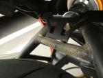
Free rear fender. All you have to do is find it somewhere along the blue line on this map. Fender was in good condition when last seen, but may have a bit of road rash now. Here's a picture of the stress point. It was clearly a bracket failure; the fasteners did not come loose. So if anyone (Craig) has yet to install this, think about how to reinforce it. I'm going to let GB know what happened. I only put about 5,000 miles on with this fender - and it gave up Saturday (just noticed this morning before work). Therefore, I retract my endorsement for this fender unless (until) a better bracket is available. Sure was pretty while it lasted.

-
Glad to hear it. Will we be seeing some photos of the gaggle?
-
When I looked at the two bikes side-by-side I thought "they'd both look better if I swapped dashes." But if (when) they fail, I think the Scura will go darker - at least the trim rings should be black, the grey face with black type might be good - or just copy your color choices. Anyway, I hope the Veglias will last a long time and that I won't need to replace them anytime soon. This might be a good time to lube the speedo cable... BTW - the first part of this project was time-constrained, because I couldn't easily get the LeMans registered in California with less than 7,500 miles showing (government rules for out-of-state vehicles, previous title was in Florida). I got a 30 day extension on the inspection, and Speedhut takes 3 weeks from order to deliver finished gauges - I got the two big clocks installed and inspected on the next to last day (nothing but a power cable so I could show the Odometer reading - and hauled the stripped bike over in the truck). Adding some miles to the broken ITI's actual reading when ordering the Speedhut made it easy to pass inspection - and kept my new California title clean and free of the "not actual mileage" warning/statement. There's a sweet irony in the creation of evidence to support what I believe is true and clear bureaucratic processes. So... pretty convenient to be able to get any starting mileage reading you want. I started at "approximate-actual-with-rules-in-mind." I noticed you started at 000000 after your restoration, which also makes sense. Docc should get one set at 100000 (one digit more than the stock gauge can handle).
-
Joshua Tree National Park this morning. 400 mile loop. Note climber on left rock face.
-
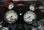
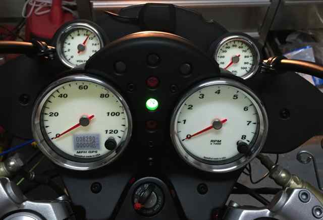
Thanks Chamberlin, these gauges are on the red LeMans (fairing still off). It came with grey-ring, black-faced ITI gauges, while the Scura came with chrome-ring, white-faced Veglias. Reasons for my color choices: I find black letters on white background easier to read with a quick glance. I like the Scura dash - and how the gauges sort of pop off it visually - so I copied the colors to the LeMans. The LeMans might get a big, white stripe on it one day... As for the extra oil and volt gauges, there's a lot of extra room behind a LeMans fairing - and nearly none behind a sport fairing.
-
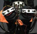
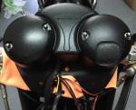
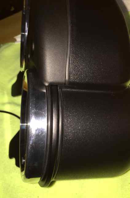
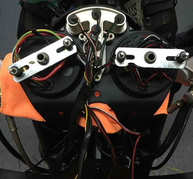
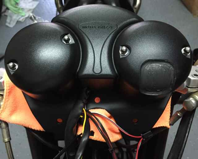
I got the gauges mounted in the stock bucket today. Here's some more detail about how I did it: 80mm O-rings - 2.5 mm thick between trim ring and dash, 3.5 mm thick between dash and bucket. This takes up about the same space as the stock rubber gasket did around the ITI gauges - and allows the little rubber gasket at top of warning lights to align correctly. Here's how all the wires and brackets aligned to fit the cup. I didn't put the inverter or the fuse inside the cups; still need to do some cable management. Here's the stock cup all fastened up. I cut a section out of a black pvc pipe elbow and glued it to the inside of the bucket with black RTV. I was a little messier than intended, so I just smeared the whole thing. Can't see it anyway. And here's the rider's-eye view of all four gauges. Still pending a road test, but I sure hope it holds up - and that the oil pressure and tach work. FYI - I think the "open sky" advice about the GPS receiver is not that important. My GPS receiver was tilted at least 45 degrees, and it quickly locked on a signal while in the garage (under a two-story house). I don't think a fairing is going to interfere with it.