Speedfrog
-
Posts
609 -
Joined
-
Last visited
-
Days Won
14
Content Type
Profiles
Forums
Events
Gallery
Community Map
Everything posted by Speedfrog
-
 What @p6x said ^^^^^^^ Sad but true.
 -
I think so, yes. One thing to know is that the factory clip-ons mounted above the T-clamp are very shallow with only one pinch bolt and most aftermarket clips are taller. The point I was trying to make is that depending on your forks setup, you might have to raise the fork legs to accommodate for the difference. On the earlier models with the top of the fork tubes flush with the top of the upper T-clamp, if the intent is to raise the bars, they would need to be mounted above the T-clamp and you would definitely have to raise the fork legs a significant amount which would change the bike’s geometry and disrupt its balance. None of that jazz with the MPH risers, they can be bolted directly to the factory clips, whether mounted above or below the T-clamp, no need to mess with the forks. They even allow for a bit of fore and aft adjustment and come with longer hydraulic lines. In most cases, when the bars are raised, longer clutch and brake lines are most certainly needed.
-
You’re right @docc, the MPH risers look a bit agricultural where the machining of the Mototec is very refined. The Mototec’s seem to be a whole clip-ons set opposed to just bolt-on risers using the original bars. It also looks like they might need the forks to be raised in order to mount them above the clamps.
-
I’ve never understood people washing their bikes before putting them up for sale and taking pictures of the bikes dripping wet... can’t be arsed to dry them, job done - they must be in a hurry to sell...
-
MPH in Houston, TX makes a set of risers that a lot of folks have used and seem happy with. Not cheap but come with a set of extended hydraulic lines. https://mphcycles.com/category/cool-stuff-we-like/bolt-on-parts/
-
WANTED Rear Carbon Fiber Fender Hugger to fit 2003 v11 Le Mans
Speedfrog replied to JAMeyers22's topic in Wanted
240 Euros as of January this year, shipping to US included. -
"Older models"??
-
Here is confirmation, of sort, that we got the right connector for our TPS: https://www.corsa-technic.com/item.php?item_id=313 And yeah, I think Sonoma, Napa or Petaluma would make a good base for a Norcal SpineRaid...
-
It was just pure luck and none of it would be possible without Google... But it also wouldn't be a proper Guzzi forum if we weren't chasing the cheapest prices available (Guzzi content)... Although at 99¢ a piece you're gonna have to order 26 units to get free shipping, just saying... I'll send you a self addressed envelope if you end up with a couple of extra ones...
-
@docc, I see you've edited your earlier post following the info I provided, but the part # you gave does not correspond to anything on that page... (C Part No: 12052641 (Black/Green Seal) OTOH, if it's only the seal you're after... Here: https://www.customconnectorkits.com/12162280/
-
I don't have the bike nor the Casper breakout harness nearby to check, but referring to the picture you posted earlier, that would be a Metri-Pack 150.2 series connector, found on page 76 of that pdf. Unfortunately there is no detailed drawing/datasheet but only nominal dimensions. However, it references all the specs between the different part numbers associated to each type of connector.
-
Found this; it might be helpful. https://www.mouser.com/pdfdocs/Delphi_Metri_Pack_150_Series_Section.pdf
-
Here is another source for the Superseal 1.5 series connectors. Cheap prices and no minimum. https://www.mouser.com/c/connectors/automotive-connectors/?series=Superseal 1.5&instock=y&pg=2
-
One of our member here, @stewgnu, created a color wiring diagram a while back. Although your bike is an earlier vintage, you might find it useful.
-
It’s actually only recently that the maximum file size you can upload has been increased to 1.46MB, it used to be only 200KB which was a real pita. It has been a great improvement!
-
The crossover pipes connecting the headers are factory standard on ‘03 - ‘04 V11’s models. They are sealed at the joints with graphite gaskets and are known to loosen up overtime and rattle... Check out this thread, you might find it instructive.
-
You ought to think DS or SM and not 2CV...
-
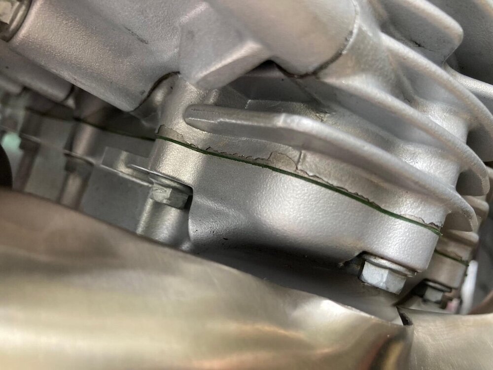
Another photo recently published by a UK V100 owner of paint flaking off the crankcase and discovered after only one week of ownership... There has been many reports online of this happening, mostly on euro bikes. Early production teething pain? What is Piaggio to do about it?
-
Here is one of the most recent discussion on the subject. It’s about the tachometer but I think you will find useful information in there on how to go about opening up and repairing instrument gauges.
-
Long Tank fuel line QD connector alternatives
Speedfrog replied to audiomick's topic in Technical Topics
Sorry mate but reading your post I couldn’t help thinking, how much help can this be? -
Long Tank fuel line QD connector alternatives
Speedfrog replied to audiomick's topic in Technical Topics
Hmm... I believe this discussion is about fuel line QD connectors... not spark plug boots. You might wanna fix that title @docc, but maybe not until you get a good night rest... -
Welcome back @docc, hope you’ve had a good raid!
-
Show your very first bike - Nostalgia...
Speedfrog replied to Speedfrog's topic in Special place for banter and conversation
WOW! That’s impressive! And it looks like you’ve taken really good care of it. -
Show your very first bike - Nostalgia...
Speedfrog replied to Speedfrog's topic in Special place for banter and conversation
The separation might not have been so “recent” if that mop is any indication...