docc
-
Posts
20,491 -
Joined
-
Last visited
-
Days Won
1,188
Content Type
Profiles
Forums
Events
Gallery
Community Map
Everything posted by docc
-
FWIW, the Centauro upper clamp appears to start with "02": 02 493 100
-
zagato and Camn: thanks for the tips! I pulled my sump and found the screen filter with a coating of paste. Also added the rubber boot to the sensor. Very tidy!
-
Buttoned back up! Started right up (after I remembered to turn the petcock back on ).

-
Heh, yeah, as jumbled as the factory fittings were, now - so many years and POs on, all bets fall off. Certainly an early clamp. I remember seeing the photos of it thinking, "Those are factory bar mount holes."
-
My only reference was Field's post from back when he was with Moto International. It would be very likely that early V11 Sports used up the remaining 1100Sport-ie clamps. Not sure why yours would have been holed for handlebars unless they were also used on the Centauro. Perhaps the only difference from xxxx3100 to xxxx3130 is that the bar mounting holes go away? Still wish someone could provide the Service Bulletin on the change of triple clamps on early V11 Sports . . . . sp838: what's your (approximate) serial number? (apparently, that Service Bulletin applied to SN > 113032)
-
That is one of the "early" triple clamp numbers listed by Field in a previous post: ["Does it read "0149 3100" or "0149 3130" (both early) or "501452" (most late)?"] Not sure the difference in the xxxx3130 clamp expect that it may not have bar mounting holes. Since the Sport1100 had clip-ons like the V11 Sport, I wonder in the xxxx3100 clamp is from the Centauro bin?
-
I guess I was looking at the Greenie.
-
Are missing turn signals in the "small cosmetic flaw" category? Otherwise, it looks like a nice, stock example and a good price. Assuming the clocks work, gearbox recall complete &c . . .
-
The neutral light might respond to a good cleaning. Something like mineral spirits and work it in and out repeatedly. You can test it off the bike with an Ohm meter from the connection to the body. It could be as simple as cleaning the spade connector with a spray cleaner and crimping it for a tight fit. Seal the boot well with Vaseline since it rides in the weather. Some have reported better switch function with RedLine ShockProof. I like the "Lightweight" for the gearbox. Looks like a blue milkshake in the sight glass! (Those clocks are freakin' gorgeous!)
-
Agostini ? As you say!

-
Yo . . . (sir), through Moderator Mirror Magic, this is the 2014 SSR thread . . . Last post of the 2013 is here. I went back through all the spine raid threads and gave them consistent titles i.e. "Second South'n Spine Raid 2006." There was no SSR in 2005 and the thread for the Inaugural Event in 2004 has been lost to the cyber-abyss of forum reconstruction. I tried to gather some archive photos from your link to WildGuzzi, but it said they either weren't there or I wasn't man enough to see them.
-
Bittersweet . . . Yet, the Futura is a really interesting ride! Hope you hooked the new owner back to V11LeMans.com. Ride well!
-
Friday afternoon? I'll bring my Smoke Wrangler . . .
-
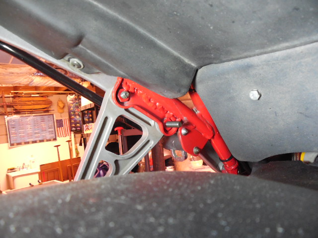
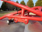
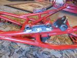
I wasn't jazzed with the Banner Red over the gray primer, so I shot it over silver and think it looks like a pretty good match!
-
Check the main ground cable from the battery to the right back of the gearbox behind the seat lock. Loosen it, clean and retighten to be certain your starter ground does not travel back through the loom.
-
12.5 is certainly low, especially for a new PC545 (should be 12.84), but not so low as to fail to crank. Check the voltage with the starter circuit engaged. Otherwise, how did you "check the starter?"
-
What is the type and voltage of the new battery?
-
Prices for nice V11 are definitely on the rise.
-
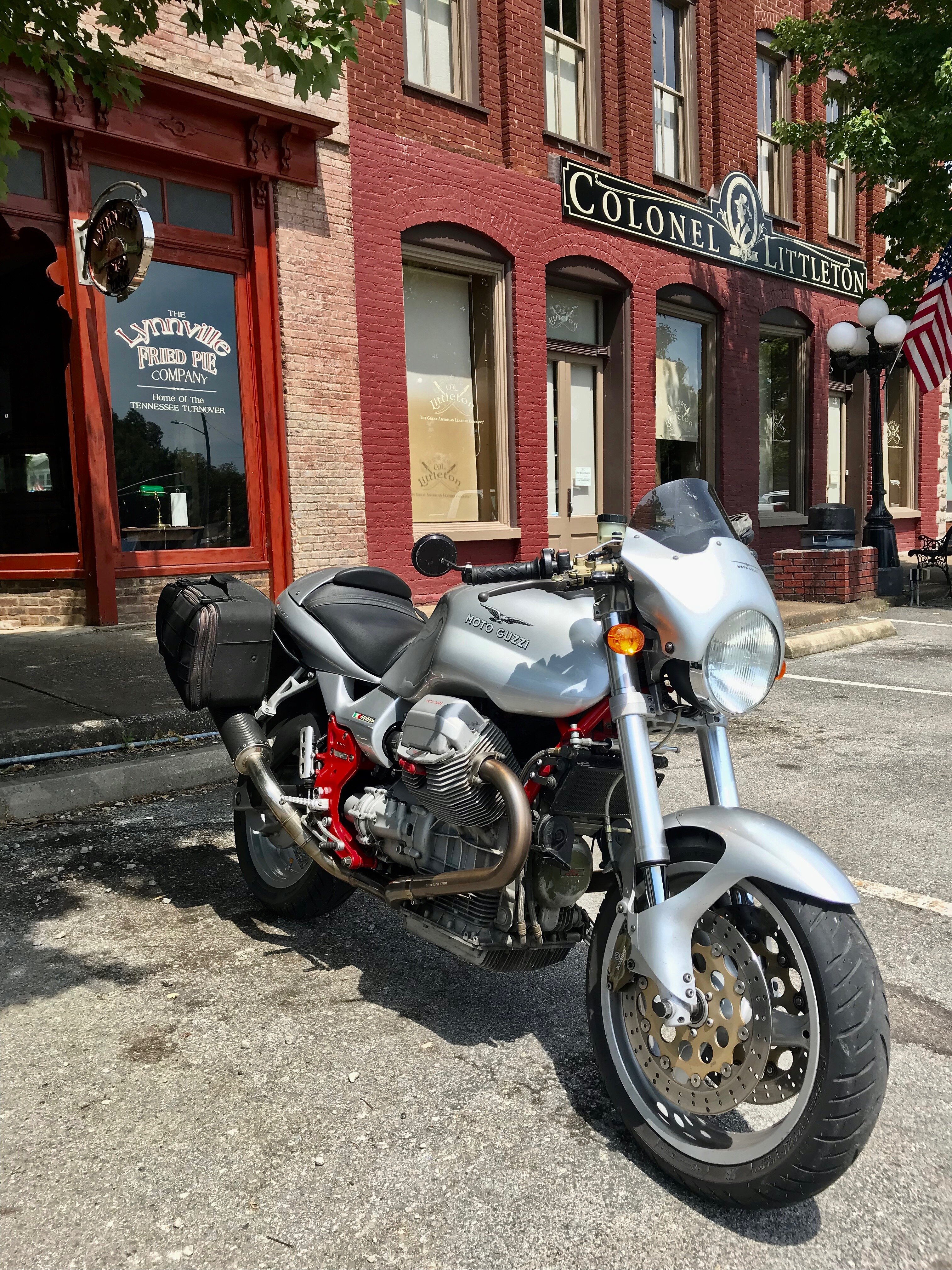
I chatted with Anthony, testa uomo, at European Motorsports in Dahlonega today. He said to be sure and let them know when we're stopping by. I'm not sure if they'll have something special cooked up for us or just need enough time to close up and get out of town.
-
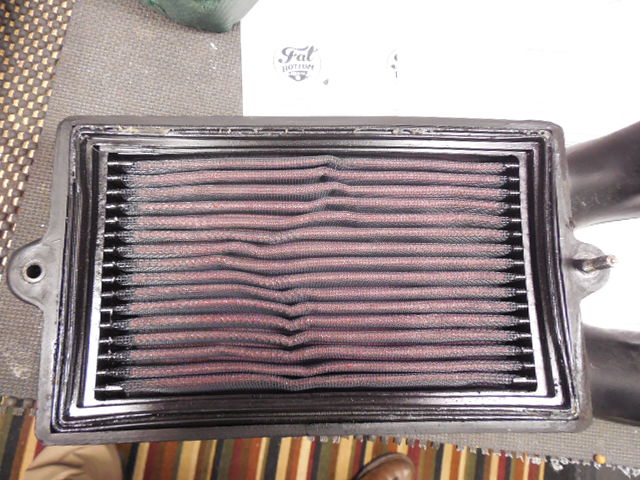
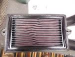
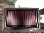
Crumpled fit of the K&N 33-2682: Perfect fit of the K&N CG-9002:
-
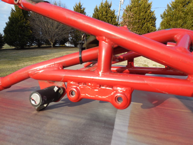
Decided to weld the other side, too. Primer's on and hoping the Krylon Banner Red makes for a fabulous match!
-
No valve on mine or other V11s having reported in. No valve on the parts diagrams either (?) . . .
-
Cool. Thanks, Ken! I saw that, but was hoping to replacing my tail light at the same time and don't see it listed on their site. Waiting to hear back from MPH on that. I thought the tail light would be easy, but not so far . . .
-
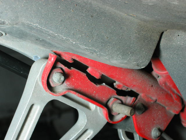
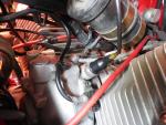
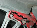
While I've got the wiring harness completely pulled loose, I checked the connector to the oil pressure sensor and found it all dry and green and nasty. Cleaned and sealed, but I'll see if I can get one of those Cali boots. Seems like a good place for one!
-
Yeah, actually I don't think my old hose is leaking. It's getting a little cracked at the top but not the bottom. I'll check with a couple of the Moto Guzzi suppliers and see what's up and probably have my parts guy restock the heater hose. Man, I really appreciate the expert advice!