Kiwi_Roy
-
Posts
2,378 -
Joined
-
Last visited
-
Days Won
62
Content Type
Profiles
Forums
Events
Gallery
Community Map
Everything posted by Kiwi_Roy
-
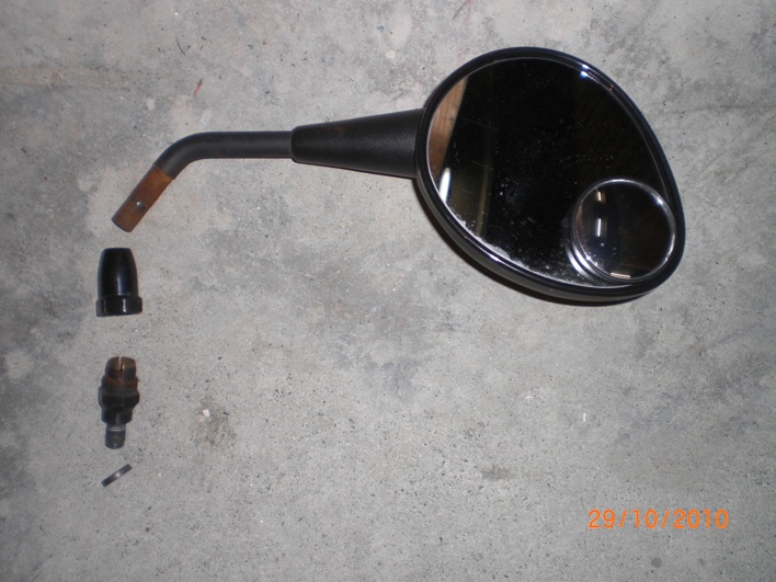
Docc beat me too it. Exploded view attached The bottom part is screwed home into the lever as docc says, then you tighten the clamp by screwing down the large nut. The steel spacer is just under 3.5 mm thick. about 4 regular washers should do it if they aren't in you box of bits, or perhaps you could shorten it's thread. The large nut will be very tight, soak it in penetrating oil for a day or two, clamp the lower bolt in a vice or a 6 sided socket and unscrew the large nut. You may only get it to move about 1/2 turn then you can wiggle the mirror back and forth until it comes out. Once you have the mirror stem out coat the parts with some form of anti rust, mine seized up solid in just a few months. Good Luck
-
I have the same mirrors. As Hubert says there is a washer about 2 mm thick but until you free up the locking nut you will have trouble getting them to stay put. To free mine I wraped the bent section of stem in cardboard and clamped it in a vice and used a ring spanner on the nut. A drop of penetrating oil will help also. Actually the stock mirrors are useless IMHO, they give a great view of your elbows and have a bad blind spot. I added a small convex stick on in the corner, now at least I can see something coming up behind. I have the stock Clip-ons, perhaps with your risers they may work better, please let us know. Roy
-
I have Mistrals on my V11 Sport, at least I think they are, ther's no label on them that I can see. The nice thing about carbon fiber, they don't get hot enough to cause a burn in fact they make nice hand warmers. They sound awesome. I don't have any experience other than that. sorry. Roy
-
What Cliff neglected to say, he builds an excelent replacement for the stock ECU called MyECU It takes the place of the ECU and Power Commander alowing you free access to the Maping It also allows for self tuning. Just ask Raz BTW, mines going great Thanks cliff and Roy I saw articles about the myECU but did ot think I had the wherewithal to assemble or above my paygrade but I tried another map that had much higher numbers at the lower revs 1500-2500 and it seems much better but not perfect so I will raise the numbers on a cloned map and up the richness more, hopefully with better results. Beyond 3000rpms I am very happy with this map ... My guess is to up the numbers in the 2000-2900 tables and see if it gets better you know, experiment. Your Idea to richen up the lower revs makes a lot of sense, tomorrow I will start playiny with this map..Thanks I made a little gadget that allowed me to adjust the TPS mV on the fly, slide up and down the map, send me a PM if you'd like to try it.
-
What Cliff neglected to say, he builds an excelent replacement for the stock ECU called MyECU It takes the place of the ECU and Power Commander alowing you free access to the Maping It also allows for self tuning. Just ask Raz BTW, mines going great
-
I found my V11 did not seem to run quite right with the K&Ns connected directly to the throttle body so I extended them using the original rubber hose from the air box. I'm sure it made a difference. It's easy to test anyway, just jamb the K&Ns into the rubber fitting. Roy
-
Looks interesting, I like the cranking health feature. I hope it is fitted with a fuse in the positive wire, if not I would fit one.
-
I don't know the Breva but I took a look at Carl Alisons drawing, it shows a starter relay (3) that energizes the solenoid in the starter. The first thing I would do is find the wire from the Relay to the starter and hang a test light or meter from that to ground. This will tell you if it's the starter or the relay. If the relay and the wire is OK the light will go on when you try to start, If it doesn't then you check back the other way. Relay bases have been a problem on the earlier bike. I assume you have checked the main connections, if not pull the main cables off the battery and give the terminals a scrape, sometimes an oxide layer prevents the current getting through, coat them with petroleum jelly (vaseline) to avoid this. http://guzzitech.com/guzzi007/schematics/2005_Breva_1100.gif Hope this helps Roy
-
I was inspired to add headlight relays by this circuit Raz provided. As an electrical type I was struck by the idea of adding a diode as an alternate source of power if the fuse blows. Normally the diodes will never conduct but if for some reason the main fuse blows you have the possibility of having some light provided by the existing wiring. Adding the relays made a significant improvement to the light brightness, I guesstimate about 10%. As it was Headlight Relays.pdf Update April 2012 Since adding the relays 2 years I discovered that wiring in the relays to bypass the original circuit has some effect on battery charging. The original wiring expects some drop (0.5 - 0.6 Volts) between the battery and where the regulator senses Voltage and compensates for it. The end result of wiring directly, the battery gets charged to 13.8 V instead of 14.4 Volts. (this also effects the kits you buy) I just revised my wiring as below, much simpler, only uses one additional relay, retains the original headlight fuse and makes the charging as per stock because it has the same Voltage drop. Modified single relay Headlight Relay.pdf Note: I don't show the original headlight relay coil wiring, there are several variations. If you are happy with the way your bike charges with an existing relay kit I wouldn't worry about the Voltage drop issue. Roy
-
That was brilliant Hubert, straight on to it.
-
it's just a 4 or 5 pin relay... any auto parts store should have one.. bring the old one in with you. Go to www.digikey.com have them for $4.59ea http://search.digikey.com/scripts/DkSearch/dksus.dll?vendor=0&keywords=Z2247 Buzzard is right the car parts stores should carry them but I never had any luck here, If you can't tell them what make and model car it comes from forget it. I suggest you only buy 5 pin, they are a direct replacement for the 4 pin variety and you can use them in any slot. They also have a switch that will work on brake and clutch. http://search.digikey.com/scripts/DkSearch/dksus.dll?WT.z_header=search_go&lang=en&site=us&keywords=CH290-ND&x=19&y=20 You can get something similar from Radio Shack c/w a roller actuating lever which you can tear off, I put one of those on a year ago and it refuses to die in spite of being non waterproof. Roy
-
It sounds like the relay base for sure, switch relay 1 & 2 (assuming you have 5 pins) As Gavo says a slight bend in the pins might help or you could try a bit of foil in the contact but you need to strip the bases down as soon as you can. Make sure you grease the contacts with vaseline when you do, this stops them corroding. Roy Relay Base Repair.pdf
-
I too have the fail to engage starter problem, I find if I go full right lock on the steering it starts every time. I assumed it was a broken wire where they flex all the time. I will fix it over the winter.
-
Sounds like a prime candidate for LED replacement. Any hitches [ie, changes to resistance/impedance/whatever making things go pear-shaped] to this idea? As Raz says, replacing the lamps with LEDs is a bit tricky but well worth it. I found simply pluging in LEDs caused a short circuit because the original lamps have a contact on one side only whereas the LEDs have a wire on both sides, I solved this by scraping the original contacts and simply soldering the wires to the leds. For the fuel light resistor use one of the old lamps in parallel with the LED, chances are it will never burn out because it's an easy service. My oil light comes on dimly in the wet but that's not a worry, I have a gauge and as soon as the switch dries it goes out again. One thing you must do is make sure the lamp is the same colour as the lenz it sits behind otherwise it will appear very dim, LEDs have a very narrow light bandwidth
-
p.s. when you remove the second fork cap the front suspension IMMEDIATELY colapses. This action takes place best on dirt bikes with long travel suspension. Don't forget the oil shooting out the top makes one hell of a mess. Block the bike up under the sump to take weight off front wheel and you should be OK. I'm pretty sure you can drain out the old emulsion if you pull the wheel out then reach up into the bottom of the fork with an allen key and unscrew the bolt. May want to tie the bottom of fork to the bars so it doesn't drop out. I would drain all the old gunk out and replace with some new oil then perhaps seal around the adjuster screw with silicone until you get time to have it fixed properly. Actually once you have the wheel out might as well just pull the fork leg out, it's easy enough. Roy
-
It's very easy to remove the fork caps with the adjustment screws, just jack up the bike to take weight off the front wheel, loosen the pinch bolt in the top clamp and unscrew the cap, Use an open end wrench or 6 sided socket as a ring spanner will mark the aluminum hex nut. Someone may be able to refurbish them for you. I know little about forks but I would be very surprised if they need replacing. Perhaps over time rain leaked in around the adjusting screws. I think you can drain the oil by taking the wheel out then reaching up from below with an allen wrench unscrewing the bolt that holds the forks together. I would try that anyway, one at a time just in case they decided to drop right out. You would need to stop the leg turning while you wrench on the bolt, perhaps a length of wood bolted on there the calipers attach. I had my forks out about a week ago, please refer to my thread "Front Fork Oil" there's some good response to my questions there. Buzzard seems like a fork guru, try sending him a PM, he seems very willing to help out.
-
My Odometer was showing just over 74,000 when it quit on Wednesday, the speedo is still working but by the way it gives a flick now and then I suspect the needle pivot bearing is on it's way out. From the various angle drive bits that came with the bike I suspect it's always been a problem, what a piece of junk these Veglias are, perhaps we need to be looking for an electronic replacement, do away with the cable at the same time. It would be nice to retain the same analog display and round shape though.
-
I just got back from my trip Vancouver - Prince George 1800 km in two days. The bike was a dream to ride, just purred along. As for the forks I had no complaint but I will pull the legs out again over winter and set them as per Buzzard's detailed instructions. I will check out the Motion Pro tool also. It sounds as though the 5 wt oil is the way to go. Thanks again for all your input Roy
-
My bike has the carbon fiber version. The PO told me they were Mistrals and they came with the For Off Road Use Only label which he said they had to have for importing to Canada. I was at the Guzzi dealer in Chilliwack, Gord took one glance at the bike and said follow me. He took me into the workshop and produced a pair of nice labels which he had asked someone to make They say Moto Guzzi V11 Sport Isn't it strange that Mistral don't stamp their name on their product?
-
I have been mulling over your post, you say spring out, can you be a bit more specific please. I won't get a chance to do it again before my trip but will do over the winter for sure. Perhaps as a public service you could treat your Guzzi to an oil change and educate us all in the correct procedure. The workshop and the owners manual both say 400 mL of fork oil but I don't think they are specific about weight. Perhaps if I had used something like a lab measuring cylinder I would have been right on, of course I didn't have one handy, the best I could do was use the scale on the side of oil container, shone a flashlight thru to get the level. BTW, I don't expect to be leaping through the air so perhaps my settings are not as critical as a dirt bike I collected the oil I drained out and poured back into the container, came to about 600 mL so either some had leaked out over the years or the PO had them serviced. The oil I drained looked OK but the ATF will match my K&N air filters at least when it leaks. Cheers Roy
-
Just noticed that it's been 2 years since I changed my fork oil. Everyone's taste is different, but afte upgrading to 0.95 kg springs (I'm ~165lbs), I've been happiest using 7.5 wt oil and a 100mm air gap. Ok, I went and sucked some out. Jacked up on the hoist to take the weight off, Slacked off on the top pinch bolts, They tighten the caps too. Unscrewed the caps to end of thread Lowered the bike slowly, the forks compressed pushing the caps up Put a narrow tube down the gap (now heres the thing, about 3" down the tube strikes the end of the inner, I don't see how you can lower the oil lower than that or even measure for that matter Syphoned out the oil until the syphon sucked air at 3". So my oils down 75mm, the bike appreciates it, much smoother ride. I also backed off on the damper screws 2 clicks, currently 6 clicks ccw, I can easily adjust that as I go I will see how that goes Off to Prince George in the morning, about 900 km Thanks everyone. Roy
-
Skeeve I did RTFM, it said 400cc. that's obviously way too much. I agree level seems the best way to go, i was hoping someone would tell me, see below Buzzard, Thanks for the tips, I will set the air chamber at 100 mm as you suggest. If I find out later that it's wrong it will be easy enough to add a bit. Gstallons, Actually I think changing the oil is quite simple, once you take the wheel at you can unscrew the bolt that holds the internals and all the oil should drain. Everyone, I must admit I was a bit skeptical when Dave told me to use ATF because he had the more expensive oil right there. He runs what you would call an independent shop, not tied to any one brand. I kind of trust him because he is a journeyman mechanic and used to own a Guzzi, so he can't be bad eh? I'm off on a road trip tomorrow' I will take it easy until I find out how she feels Thanks Roy
-
I changed the oil in my forks Dave, the guy in the local shop recommended transmission fluid which was cheaper than the fork oil he had in stock. The manual says add 400mL (it doesn't actually say "In each leg") but I found the right fork seemed to be fairly full, just a couple of inches from top with no weight on, If I pushed the fork up it would run out. I spoke to Dave and he assured me 400 sounds about right for an inverted fork. There is very little travel with a sudden stop and the ride seems a bit rough. Also by the time I had spilt a bit and generally made a mess when I tipped the old oil back into the bottle I ended up with about 600mL total I am tempted to suck some back out, is there a level I should have it at e.g. XX mm from top? Can I do any harm by having the level a bit low? Thanks Roy
-
Here in NA the EBC pads seem to be used by several bikes, heres the catalog page c/w dimension, these are the ones I ordered. The trick with tightening a strange screw is tighten it till it strips then loosen it half a turn, just kidding. Roy Page 99 of EBC Catalog.pdf Page 171 of EBC Catalog.pdf
-
I hate to be a wet blanket but is that thing legal? It doesn't seem to have a plate illuminator, Reflector/ Sure looks nice though. I hope I'm wrong