

Kiwi_Roy
-
Posts
2,378 -
Joined
-
Last visited
-
Days Won
62
Content Type
Profiles
Forums
Events
Gallery
Community Map
Everything posted by Kiwi_Roy
-
No they should only change slightly with revs as the battery voltage goes up a bit. Are you using regular lamps, old fashion incandescent that is? Usually indicators flash faster if there's a lamp out, perhaps you have a bad ground to the rear lamps. Check that your voltage regulator is well grounded and the battery ground behind the seat release key is tight.
-
Thanks man. I'll check that out. I think swapping the relays is a temporary fix, I'm sure the real problem is loose or coroded contacts in the relay base. The good thing is it's easy to fix Follow the topic http://www.v11lemans.com/forums/index.php?showtopic=15718 or go straight to the source http://www.v11lemans.com/forums/index.php?app=core&module=attach§ion=attach&attach_id=10441 Just pull the contacts one by one so you don't get them mixed.
-

V11 Turn Signals, Dash & Stop Light Problems
Kiwi_Roy replied to shagerman's topic in Technical Topics
Thanks for the update. I have been troubleshooting electrical problems for the last 45 years and still the Guzzi wiring has me scratching my head. It's so conviluted with some circuits relying on several fuses to operate. Just as well we all love a good challenge. -
As Docc says we are ready to help. If the 30 Amp fuse was blown the battery would go flat for sure, try giving it a good charge, maybe all it needs. My 30 Amp blew, It actually welded itself into the socket, that's a sure sign of a loose socket not over current. You will find everything you need and more right here. Is your 2001 green like mine? Ooopps i should have looked at the picture Roy
-
V11 Turn Signals, Dash & Stop Light Problems
Kiwi_Roy replied to shagerman's topic in Technical Topics
Another thing. Here in Canada we don't have the light switch on the left hand cluster, by law the lights stay on while the engine is running. If you have that switch, all the aforementioned lights pass that way along with the headlight. I bet a dollar to a donut that's a source of much grief. Turn the key on and flick the handlebar switch back and forth to see if the lights flicker, if so you need to pull it apart and clean the contacts. But check for power at F6 F7 first, if not there try flicking the key back and forth, I had to strip mine down and clean it, the grease goes hard after a few years. You can check the contact resistance using my Test Point Layout, it should be less than 1/2 an Ohm from F4 to F6 and consistently the same each time you operate it. It's possible for the headlight to be on without the other lamps because the circuits are separate. The diagram in the back of my owners manual shows a park switch on the key in series with a park switch on the bars, those crazy Italians!. Roy BTW, I posted the drawing here because the original had a typo, Note 4 said Test Point Layout August 18 2010.pdf -
V11 Turn Signals, Dash & Stop Light Problems
Kiwi_Roy replied to shagerman's topic in Technical Topics
Ok, the turn signals, tail light and speedo/tacho lights are powered from Fuse 6 Did you check there for 12V? Do you have a wiring diagram, if so which one are you using? What are you using to test for voltage, a meter or a test lamp? I still prefer a lamp when tracing a fault like this, it loads down the circuit whereas a meter will indicate even across a bad joint. I presume your bike still runs which means you have power to the ignition switch. From there it runs back to the common point of F6 / F7, thats the first place to check. When electrical troubleshooting just go one step at the time. If you print out the drawing I posted a few back you will see that the power goes from battery to ignition switch, from ignition switch to fuses so you work your way along either from the battery until you no longer have power or from the lights back until you find power. I sent you a PM Print this out while you are at it. http://www.v11lemans.com/forums/index.php?app=core&module=attach§ion=attach&attach_id=10455 Roy -
The 4 & 5 relays are both essential for the bike to run and they both use the same contacts so there is no reason why a bad relay will run in one spot and not the other. next time use say 2,3 for 4,5 I strongly suspect it's a bad connection in the base, pulling the relays gave it a bit of a scrape, as soon as you get a chance pull the connectors one at a time and tighten them up. I can't stress enough the importance of having some grease on the contacts, it protects against oxidization (corrosion), get a tube of vaseline from the chemist. I have 5 pin Omrons in all spots.
-
Beautiful bike. The previous owner put K&N filters on as I have just done, I love the open frame look. The vibration shouldn't be too noticeable, perhaps the throttle bodies are out of sync. Some guru please comment. See that big wire loom that loops under the seat release key if you snip off the ties you can move it up under the tank and seat out of sight, you don't have to disconnect anything just loop the surplus wire under the tank where the air box used to be. Enjoy your new Italian Girlfriend. Roy
-
V11 Turn Signals, Dash & Stop Light Problems
Kiwi_Roy replied to shagerman's topic in Technical Topics
First check. Do you have power at Fuse 6 & 7 from the ignition switch? If Not Sometimes with age the grease in the contacts goes hard keeping them apart. I had that with my V11. You can check the contact resistance by pulling fuse 4 and measuring to the common point at F6/F7 if it's consistently less than say 1/2 Ohm it's ok otherwise the switch comes apart quite easily although you do need 3 hands from memory. Clean out the old grease and put back some vaseline or similar. From the switch it goes through a large connector at the front of tank check for corrosion there. Look at the Carl Allison drawing it will show the connector and wire colour. My drawing doesn't show the connector. Sometimes after years of flexing back and forth a wire will become brittle and break inside, that would happen where it flexes at the front forks look for any point that bends sharply when you move the bars back and forth. A broken wire will stretch when pulled hard. BTW if you lay the Test Point Layout drawing on the bike the orientation for fuses and relay pins should match, that's how it is on mine anyway. Test Point Layout May 17 2010.pdf -
Update . . . I haven't had a Veglia apart but some of the other speedos I have seen have the needle pivoted in the center of the spinning magnet. If the lube starts getting a bit dry or sticky it drags the needle around causing it to swing wildly, a kink in the inner cable also causes it to wind up then let go. Try spinning it with an electric drill that should sort out if it's a sticky bearing or cable. Mine quit working a week ago, when I bought the bike the cable was chewed off at a kink in the outer. I never had any luck getting a replacement from the dealer so I purchased a generic car cable. I would have replaced the outer but the car cable outer is not flexible like the original. I took out the kink by stripping the jacket off and heated the outer with a propane torch. I simply re-covered it with plastic tape. I flipped the outer around so the damaged portion is where it doesn't need to flex under the tank. My first attempt at making a new inner lasted a few months then chewed off where I tried to file a square end. After several dismal attempts to get a square end I finally came up with this method. Heat the end until red hot to burn off the oil. Once cool rub in some JB Weld (2 part epoxy metal replacement) then let it set overnight. The epoxy holds all the strands together for easy filing, solder would work too perhaps. Hold the end horizontal in a vice so its just proud then file a flat about 10 mm long by 1mm wide. Spin it round 90 degrees and file another flat. The vice holds it at a perfect 90 degrees. Do that twice more and you have a perfect end. not square but circular with 4 flats. I use this end at the gearbox because the cable there is straight so it doesn't have to flex, I'm sure heating it red hot didn't do the metal any good.
-
Don't use water for goodness sake, use engine oil. It's more viscous (better damping) and won't harm your donkey if it sucks it in. You won't need restrictors with oil it. The easiest way to get the oil in is dip one end in the oil container and suck on other. For connecting to the throttle bodies get a couple of straight 6 mm grease nipples and remove the spring & ball by grinding the threaded end. You might try drilling with a 1/4" drill or filing but mine were really hard. The plastic tube will become soft and drop off when the engine heats up so wire it in place or use a short length of rubber hose. If you can get it balanced within 6" or so that's great, the manometer is much more sensitive (and accurate) than usng two gages.
-
Once I saw all the fun you guys were having I thought "I just have to try that", my fluid was a dark brown colour. I found my 1/4 sockets were not deep enough to grip the bleeder but a 10 mm ring spanner did the trick. The only way I could reach in was thread my hand up just above the crossover on the brake pedal side. Once I got the wrench in place I was able to operate it from the opposite side while working the lever. It sure helped that I have taken off the airbox, I can now see all sorts of hidden treasure
-
Geezz, you're not having much luck with that bike, it must be the colour, I know a green one you could do a straight swap for. If it's just the cable, give me a call. Give me a call if you're looking for an all day ride on Saturday. Roy
-
When mine did this turning the kill switch off and on again restarted the engine, I swapped the relays around and the fault did not return on my next ride, so I put switch cleaner in the suspect relays (there is a small hole on the underside)and swapped them back and as yet the fault has not returned.Most faults like this are relays but the side stand, clutch switch and ign switch wiring have all given people here issues. That's the advantage of indicator lights on the relay base, it shows at a glance if the relay contact is closed, otherwise it's hard to tell. I think a lot of times the relays get a bad rap because it's easy to blame something you can't see. I don't know how many times I have tried to start and found the kill switch partially pressed. Perhaps I should put a light there as well eh!
-
Thanks Felix, I will pick up some larger hose and the K&N breather fitting. I think I will leave it poking out just in front of the crossover to one side of the wheel track.
-
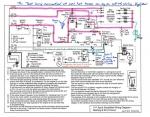
Heres the same drawing I have highlighed to show what's needed to make the bike run. I have shown a lamp on the right hand side (I use a 12V LED). With this on the bars if your bike so much as stutters you can see if any of the highlighted stuff to the left failed. If it does then you move the lamp connection point further left thus zeroing in on the fault. It's much easier troubleshooting an intermittent fault this way instead of waiting for it to fail then pulling out your meter. I also sketched on Dan's note 2, I can't see why it didn't work. When you get more time I suggest you add a new fuse with a heavy gauge wire to the headlight area. Use a couple of your old relays for High and Low beam this brightens up your night no end as it bypasses lots of wires and contacts. Raz gave me a circuit using a pair of relays & a pair of diodes thats real nifty. You don't need bases for the relays, just spade connectors. BTW, you didn't say what you did to get going again after the total failure, that might be a valuable clue. Cheers Roy
-
-
Yes, they are 6mm Buy a couple of straight 6mm grease nipples, zerts or whatever you call them. Grind the back end a little so the spring and ball pop out. You might be able to do that with a drill or file but mine were really hard. Just a side note, plastic tubing will get soft and drop off once heated up, try to use some rubber hose for the last few inches or wire the plastic tube in place. If you are making your own manometer the attached may help, Use something like oil that won't damage the engine if it's sucked in. I found 30 oil has about the right damping. Dip one end into the oil bottle and suck it from the bottle into the tube until the straight section is about half full If you get air bubbles in the oil suck on one side then the other the air quickly works it's way out Roy Carb Sync Tool.pdf
-
So what to do with the breather hose
-
I'll stand back and let someone else with more experience step in
-
I would check relays 4 & 5 for sure if either of these is bad it will stop you in your tracks at the least move these 2 to another spot. Look at the FAQ - "Relay Base Repair" that explains how to get the contacts out. Could be your sidestand switch also. Connect a small lamp to the hot terminal of a coil and ground, have it up at the bars where you can see it go off if it cuts out again. I have a 12V LED I poke through the hole in handbrake lever. I just jamb the wire in a relay socket or wherever I suspect. Intermittent faults can be very hard to pin down, I have 40+ years of practice, but I still find it hard sometimes. Good Luck Roy
-
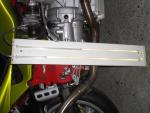
It's very easy to raise the idle, see the tread on TPS setting under the FAQ forum. If you can do your valves, you can do this. Balancing is a bit trickier but the FAQ tells you how, heres a picture of the tool I made. Use engine oil, if it accidentally gets sucked in no harm done. I made the connection to throttle body with 2 x 6 mm grease nipples, grind the back a little to remove the spring and ball. Make the final connection to the nipple with rubber hose, plastic gets soft and falls off when hot. Don't expect to get the two columns closer than about 150 mm from idle to 3000 revs. Have fun Roy
-
A ceramic holder would be ok but I think the regular plastic should be too, that's what I have in my after market and no problems. Your old connector was loose, it melted around just one of the pins. Notice the colour of the lamp pin compared to the one adjacent, looks like it might have been red hot. BTW, no I don't think this caused the regulator problem, the headlight would be drawing less current with a bad connection, I think it's very unlikely you would get a short there. Replace the bulb and holder, you will be as good as new.
-
It's quite damp here in British Columbia but I see no sign of emulsion in my engine. perhaps you could try a desicant canister between the spine and where it joins the intake just below the filter. Isn't that where moisture would enter? BTW, I'm new to Guzzi so don't take me too seriously, I may be out too lunch
-
Follow this thread, I think you will find the answer http://www.v11lemans.com/forums/index.php?showtopic=15778


