Kiwi_Roy
-
Posts
2,378 -
Joined
-
Last visited
-
Days Won
62
Content Type
Profiles
Forums
Events
Gallery
Community Map
Everything posted by Kiwi_Roy
-
My V11 has developed a sneeze at low revs, I don't think this is ECU related because it also does the same with a different unit. It will idle quite nicely then occasionally seems to kick back and stall. It does the same under way at higher revs and low throttle setting but of course doesn't stall. I did a check to make sure I wasn't loosing voltage at the ECU, no problem there. I was wondering if it's possibly an injector sticking. The bike has done 71,000 km, as far as I know the injectors are original. How long will they last? Thanks Roy
-
I have a couple of nice engraved decals for my Mistral mufflers. I have tried several different red paints to pick out the engraving detail but each time I polish off the surplus paint with metal polish the sub surface paint comes with it. Just doesn't seem to want to stick. Whats the secret? Thanks Roy
-
Yes you are correct the 1.564 is the open circuit or Diode in reverse Voltage, 0.448 0.428 are the forward bias Voltages. What you see is very similar to what I get on mine, I think your diodes must be ok, you would see 1.564 in both directions if the diode was open circuit. Perhaps test it again after a run while it's hot Make sure it's well grounded. It is possible to change the regulator voltage, there's a trim resistor on the back side of the circuit board thats quite easy to uncover. My Voltage is a bit low as well so I will adjust it and post a picture. Roy
-
5 Years seems reasonable for a battery, my 2001 had the original Spark until late last year with a sick regulator. The bike was stored in a container for over a year, who knows with a good regulator and better care it might still be going. The replacement Yuasa Failed over the winter in spite of the TLC I gave it, obviously faulty manufacture, would drop to 10,5 Volts just after recharging. I agree with Raz, the regulator is solid state, there's no reason it shouldn't last the life of the bike, it's components are undersized in my opinion. Have you done the simple diode check, Yellow to Red?
-
And here's the circuit diagram Emry said "When using a "open" (SCR is used to open the current path) style recitifier voltage can only be regulated in half waves. For the regulator to function the SCR's must be turned on, they will remain in this state until the voltage crosses 0v, at which point they will open, thus cutting output. This can make output filtering very important as voltage levels can swing wildly at low frequencies" You can see this on the right hand side the waveforms are what I saw with my scope, really lumpy eh! Regulator Schematic.pdf
-
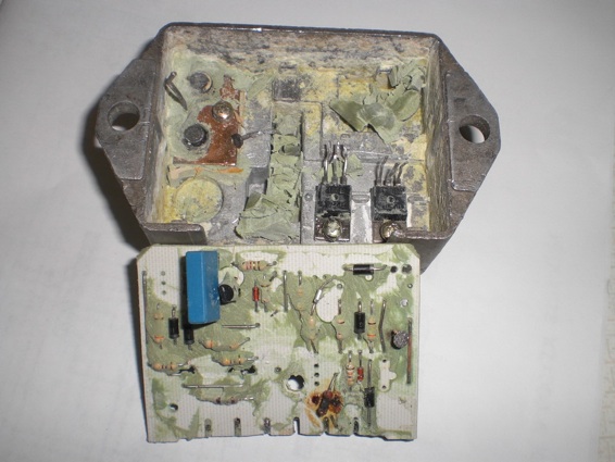
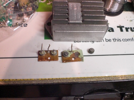
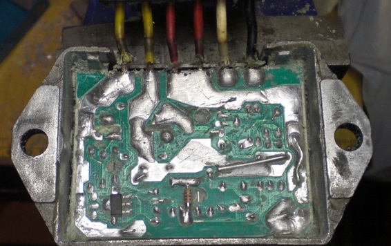
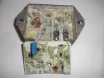
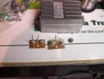
OOOppps the server crashed, i hope it wasn't me The next picture shows the board right out. Inside the case at lower right you can see the two SCRs, these are the other half of the bridge. To the right of the diodes what looks like a tack is a diode lead that came off, the other diodes lead is still attached to the circuit board on the right hand side (it's flipped over) The transistor is missing in the middle of the board, although not attached to the case it wants to stay behind. You can also see a burnt out resistor on bottom edge of the board, that drives the charging light. I suspect the lamp was shorted out at some time. A couple of parts got destroyed in the process but they are readily available. Picture 2 shows a good pair of diodes alongside the pair I just took out. Actually the second pair is repairable, just needs cleaning up and soldering back together.
-
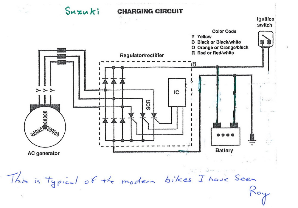
Makes perfect sense to me, of course I'm easy Actually I posted it on an electrical forum I use all the time. This guy is a guru. What he says is it's producing current without producing power. The current still heats up the circuit but it takes little HP to produce it. When it's charging the battery it's using more HP, you'll have to trust me on that. Skogsgurra (Electrical) 22 Jul 10 11:53 The impedance is mainly inductive so the shorting produces reactive current, which doesn't heat much, nor does it load the prime mover. Shorting with triacs is still used. At least in trial bikes. That's where I have seen it. Heres the charging circuit from my 2005 Suzuki S50, I have seen others similar
-
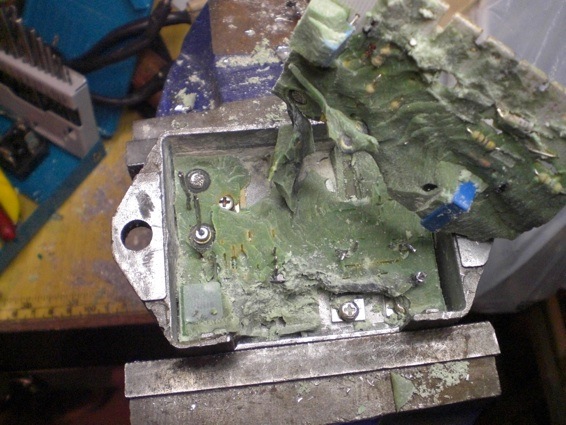
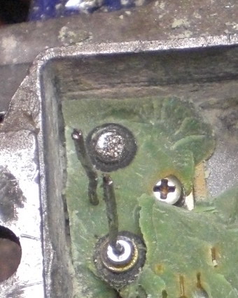
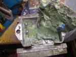
The trickiest part of the process is removing the circuit board. You need to slice all around and under as much as possible using the grommet location to poke the knife under. The first picture shows the board finally out The second picture shows typical arcing, the diode lead is just soldered on. Im not sure what causes the solder to melt, probably an overload then it starts to arc away. With one diode not properly functioning that's probably when you notice the charging seems to be weak.
-
This might be a good spot to start a side topic on repairing the regulator. Here are a few pictures taken in the process The epoxy is quite easy to remove, you just need patience. I would describe it as a bit like sugary toffee to cut through Once you have the board exposed you need to unsolder the diodes and SCRs


-
-
I guess it's easier with a 3 phase alternator since 3 phase is allways putting out current and you need the current to pass through zero for an SCR to turn off. I tested my Guzzi out of curiosity I think I got something like 27 Amps AC shorted out. Perhaps shorting out doesn't consume as much power, I'll have to think about that, I saw 27 Amps but no Volts (no Watts). The 27 Amps will certainly heat up the coils.
-
Sorry, I just noticed your question. The Yamaha charging system is quite a bit different The Yamaha alternator and I think most other bike alternators are 3 phase (3 wires), the Guzzi is single phase (2 wires) A 3 phase system gives a much smoother DC from the regulator because there is always one set of coils generating Voltage 120° apart whereas the single phase alternator stops sending power to the battery for a good portion of the cycle. Because of this gap it needs to send higher current pulses to make up for lost time. The Yamaha (& Suzuki) regulator operates by shorting out the alternator coils when the battery is up to voltage The Guzzi regulator operates by opening the circuit when the battery is up to voltage. I guess in theory it would be possible to convert the guzzi to 3 phase but I think at the very least it would mean a new stator. If someone has there stator out they could count the coil slots, the number would have to be divisible by 6 I think or at least by 3 I should point out I'm not a motor winder. You could just try the Yamaha regulator leaving the third input wire disconnected, it might work but there again the single phase Guzzi alternator might cook it, or cook itself. Myself, I decided to design my own regulator using much beefier components 50 Amp instead of about 25 Amp. I have most of the parts, just need to find the time.
-
I just changed my 2001 Spark late last year I think it may have been OK still if the PO hadn't stored it for a year and the regulator hadn't quit. I ended up paying $190 for a Yuasa in a panic so you may want to have one on hand while you can shop around Get it dry with the acid to add. The Yuasa is quite simple to commission. Roy
-
I observed -3 at idle after overhauling the regulator but perhaps I'm idling too slow. If anyone wishes to add an ammeter look at the drawing I posted #2 from top. The proper location is "Position 2", this will show the net charge (current to and from the battery not including starter) Under the seat would be a good location for a small ammeter thus keeping the wires short hard to see while riding however A digital mV meter could be added up front using a simple shunt under the seat e.g. 10 mV per Amp, that would require just small wires from the seat to dash, I could draw that up if anyones interested. I think mV kits should still be available, failing that a small cheap multimeter would work. Roy
-
No, not in the Ducati regulator, the 2 SCRs are part of the bridge they turn off breaking the circuit when the Voltage is up. On my Suzuki they shorted out the alternator as you say. Here's the full circuit and explanation, my interpretation anyway. Roy Regulator Schematic.pdf
-
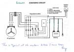
Here is the basic circuit. The 3 regulators I have pulled apart have had a bad connection to one of the diodes at top of drawing. Test your diodes with a multimeter on diode range. You should see about 0.5V when you connect the red probe to one of the yellows and the black probe to the regulator red. Open circuit when you reverse the leads. If you don't have the diode tester you can check with a battery and lamp. The other drawing shows the readings I obtained after overhauling my regulator. Note: Pulling the headlight fuse doesn't save power, the regulator picks up 12 volts from that circuit as a reference without it there will be no current and the battery will go flat. If you need to conserve power unplug the headlight at the steering column or pull the lamp. Roy Regulator Basic2.pdf Charging Circuit.pdf
-

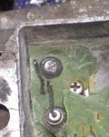
Found doing a Tranny cover/Pawl spring inspection
Kiwi_Roy replied to mznyc's topic in Technical Topics
It wouldn't be a magnet by any chance? Sometimes one is fitted to the drain plug to catch any stray iron floating around. -
I work with pressure regulators all the time. Applying a vacuum will lower the pressure but only by the equivalent of atmospheric pressure say from 45 - 30 psi. Interestingly there are guzzi documents that show the spiggot connected to the inlet manifolds which would lower the fuel (pressure) flow under low throttle not by much though. I think that must have been dropped early on. and if you tried it would throw the map out.
-
The valve you see is the pressure regulator, it sets the injector pressure, about 45 psi I think. My bike had a section of large hose slipped loosely over the fuel line from petcock to the pump, I suspect this was to shield it from the heat coming off the cylinder head, perhaps to solve a similar issue.
-
I think reading Ratchets many postings was one of the reasons I decided on MyECU so I could freely make adjustments to the effect the different sensors have, it's still a black box, but at least it has a window. At one stage I tried changing the TPS voltage on the fly to see how it effected performance, now I have access to map values I can see I probably didn't change the voltage enough to have a noticeable effect. Roy
-
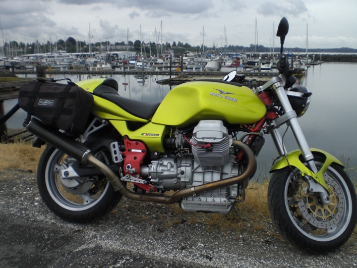
I have Mistrals on mine put on by PO, they look exactly like yours except they came with a dirty aluminium label riveted on "For off road use only". needless to say I got rid of those and they are a little scratched where they came in contact with the road a couple of times but I love the sound. I like the look of your intake filters without the side covers, what are they?

-
I should mention I got my kit going, not perfect yet but shows a lot of promise. To make use of the OEM ECU and my Power Commander I permanently wired the two together and installed in a metal box that fits in the tool tray as spare. Because I had to rob the pressure sensor I simply wired in a couple of resistors to give me 4.1 V (approx sensor output a @ Sea Level). I have taken the bike over 2,500 ft using this with no obvious effect. For some reason the bike cuts out once hot, I suspect it's something to do with the sensor fitted to RH cylinder. If I flip SW2 ON it runs OK Can someone please explain what the table marked Flags is about? I am thinking about an LC-1 kit but confused by the myriad of options when I google LC-1 Innovate Motor Sports Do I need an Optimizer to use the LC-1? Roy
-
Yes the type of spring nuts used to hold the reg in place shouldn't be relied on. The ground has to carry the total alternator output current. As Murray points out if you loose say 1/4 Volt between the regulator and chassis your battery will be low by the same ammount. I drilled a hole in one of the fins and put a heavy duty cable between there and a timing cover bolt. The Ducati regulator operates by opening up the charging circuit whereas some others operate by shorting out the alternator. Most alternators are 3 phase but the Guzzi is single phase so I would be a bit careful about substituting an after market regulator. If anyones into repairing a regulator send me a PM.
-
Hi Tom, Yes, I took some readings off my V11 after re-building the regulator with a new Yuasa battery. If you look back up the thread at my previous post you will see a pdf attached. Regards Roy
-
Heres a few more tips, I did some tests after repairing my regulator. Charging Circuit.pdf