Kiwi_Roy
-
Posts
2,378 -
Joined
-
Last visited
-
Days Won
62
Content Type
Profiles
Forums
Events
Gallery
Community Map
Everything posted by Kiwi_Roy
-
Yes- it's the result of a poor connection. Good thing is you will be able to buy another connector with short leads in any auto store, or an auto wrecker for that matter, just connect it to the existing wires with crimp links. You may need to replace the lamp too if it's been arcing. it's a simple matter of replacing the lamp connector.
-
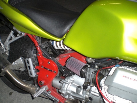
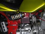
OK I have my K&Ns on, love the look, now the spine and rear suspension are exposed, If anyone else likes this look the 10 or 20 degree might look even better, I went for the largest one in straight. Sorry about the dirty bike, just went for a quick spin in the rain. Just one thing, what to do with the crankcase breather & temperature sensor. For the moment I extended the breather down below the exhaust with a length of plastic hose and tie wrapped the sensor to the frame under tank. I welcome your suggestions for a permanent fix Thanks Roy

-
I adjusted the valves as you suggested, the difference is like night and day. I went on a long ride today and hardly had any sneeze problems, I will try the mixture next, hopefully that will cure the rest. I set the valves as per manual 0.1, 0.15 about the same time I switched to MyECU, so it got more than it's fair share of the blame What's your theory behind this cure?
-
I'll second that, I was having the same sort of problem with mine, valves adjusted as per the manual Raz told me to increase to 0.2 & 0.25mm, what a world of difference,
-
Put me down for long sleeve Black, Large Great idea When do we see a picture?
-
Updated drawings: Relay Base Repair.pdf Relay Base LEDs.pdf
-
Oh dear, It seems I'm the only one that went with the straight flange. I looked at the RU-1410 but it was out of stock in US, hopefully I will be ok with the straight ones Roy
-
Thanks Raz, I will try the cell a bit richer How was the holiday in France?
-
No, sorry The power is just not available all the time, Pulse Width Modulation usually requires steady DC to work. It could be used with a 3 phase alternator. I assume you are thinking something like the power supply in a computer. The bike doesn't really need anything that complex because it has the battery that acts like a huge filter to smooth out any lumps. Here is a sketch of the waveforms, Single Phase compared to Three Phase. Hope you find it interesting. Roy Regulator 1 or 3 Phase.pdf
-
No, I plan on completing my own regulator at some stage, probably this winter but in the meantime I will leave the pot in place so I can tweak it. If anyones considering doing the same here's a better way a/ 1 kOhm fixed resistor b/ 20 turn trim pot 1 k, 2 k or 5 k would do. c/ After removing enough epoxy, drill a hole through the case for the trimpot adjustment screw. d/ Remove existing trim resistor e/ Wire the trim pot and 1 k resistor in series in place of the trim resistor arrange it so when you turn the trim pot the resistance becomes less. f/ Fill over the trim pot and resistor with fresh silicone sealant. Start with the trim pot about half way, run the bike for a while then adjust it up or down a couple of turns until it's where you want it. Be patient it takes a while, could take several days to get it just right. I think it's best to mount a Volt meter where you can see it while riding, I set mine so it reads about 14.5 Volts maximum. It seems that just reving the bike is somehow different. I simply taped my multimeter to the tab on the fuel cap. The voltage varies quite a lot as you are riding, I see 12.7 to 14.5 Volts (don't tell me my 2nd Yuasa battery in 6 months is on it's way out)
-
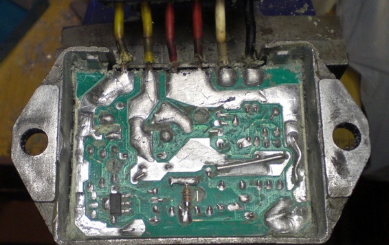
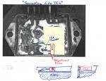
Update: OK, today I pulled my regulator off and exposed the trim resistor. I unsoldered the resistor and found it to be 2.5 kOhms (2,500 Ohms). The main resistor, the one you can't see is 540 Ohms. I wasn't sure which way I needed to go so in place of the 2.5 kOhm resistor I connected a 1 k fixed resistor in series with a 5 k pot so I could try different values. It turned out that reducing the resistance increases the voltage. Preliminary testing shows that I get a good range of adjustment with a 1kOhm fixed resistor in series with a 500 Ohm pot. I extended the circuit with a couple of wires and mounted the pot behind the horn out of sight. I think the ideal arrangement would be a 1 kOhm fixed resistor in series with a small 20 turn trimpots also 1 k it would be easy easy to drill a hole in the case and have it exposed at the front to allow for easy adjustment. I couldn't find one in my junk box or that's what I would have done. Alternately you can just try different values of fixed resistor until you get the right one then solder it to the board and cover up. Don't be tempted to use a resistor less than 1 k thinking that your charging will be better, the battery needs a while to adapt to the new voltage and you don't want to cook it. Note: The damper mounting bolt is a good place to mount your regulator while you mess with it. Finally, Make sure both your diodes measure OK, 0.4 - 0.6 Volts on diode tester. Make sure the regulator is well grounded to the chassis Hope this is of interest. Roy

-
Why don't they just come out and say "NOT SUITABLE FOR GUZZIES"
-
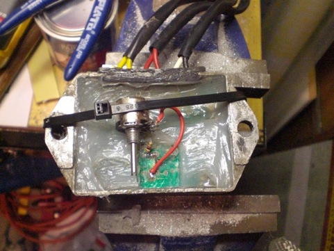
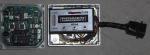
No, you don't need to pull the circuit board, just uncover the trim resistor thats on the exposed side the one you see in the picture bottom center. If you remove an inch square section should be enough. I will do mine and report back, I have been meaning to tweak it up a bit for a while anyway.

-
If you are just playing around, why not use a 30-50W trim pot? You could dial it in to your system. I think a 2k in series with a 5k trim-pot would be more practical and a permanent fix, 1/4 Watt components will be adequate.
-
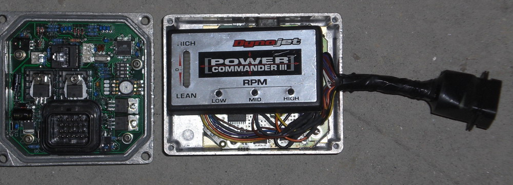
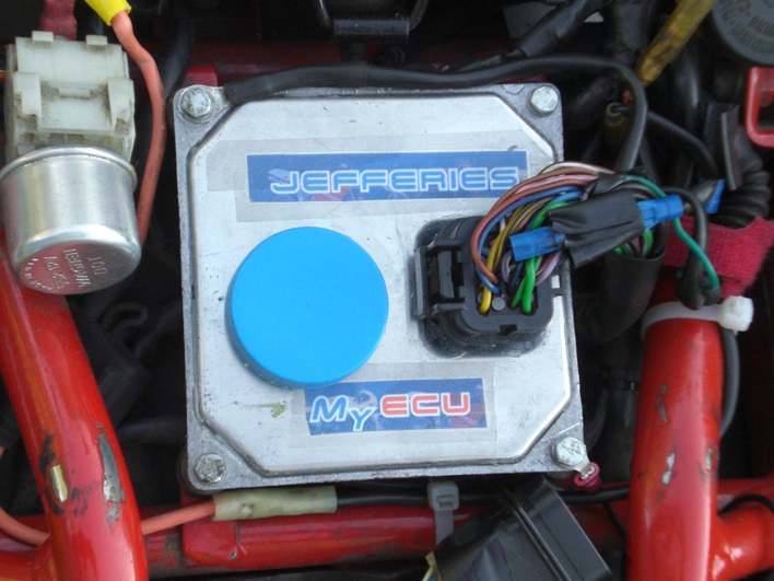
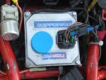
Hi Roy, That ECU is mounted upside down and can be damaged by the seat base flexing and contacting the connector. I lost a stock ECU due to the PO of my bike mounting it like that. Flip it over so the connector is facing down. Oh, I never knew that, it's the way it was when I bought it. Makes sense though now I think of it, the wires do get crunched a bit. Thanks for the heads-up Roy
-
Yep, and that is why I'm still wavering between the myECU and Tuneboy. With Tuneboy, I at least get started with the original map, that is, I can still ride!! Then again, if I wait a coupla months, it'll be snow and ice everywhere and I can start fiddling with the myECU safely inside in a garage, waiting for the next spring... I carried the original in the tool tray for a while, I had trouble with MyECU because I had left a resistor out, I had a Power commander so I cut the wires off it and soldered it directly to the original ECU. A couple of resistors in place of the pressure sensor i removed works great
-
Very glad to have made somebody's day, though. With my level of expertise, I'm looking forward to installing a myECU. New stories abound, for shure! That's good, I was wearing Cliff's patience pretty thin. I will be able to watch while someone else asks the stupid questions / makes stupid mistakes. Mine's not perfect yet but reached the point where I have closed the lid & no longer take the stock with me as a backup, No going back now that's for sure. Congratulations
-
I started my project before I pulled the first regulator apart but I did steal a few ideas after figuring out how the Energia works. Mine is just a full bridge rectifier followed by a single SCR and a firing circuit. The potted bridge rectifiers are good because you can bolt them straight to a heatsink without having to worry about insulation. The original thought was to phase angle fire the SCR like they do in electric drill speed controllers but I will probably start by just skipping 1/2 cycles like the Ducati does. As I said before as a temporary (get me home) measure I simply rectified the AC and connected it to the battery, this resulted in far too much current pushing the battery over 15 Volts so I am thinking the alternator puts out plenty of power. The weather is way too nice to be stuck in doors so I will be out there riding instead of working on my project. In the meantime if anyone would like to try adjusting the regulator look at the attached picture. The resistor you see at the bottom center is a trim resistor in parallel with another on the other side of board, Simply take a sharp knife and slice out the epoxy, the worst you can do is damage the resistor. The combined resistance of this and its partner on the one I just measured is just under 500 Ohms, The resistor on circuit side is 530 and the trim resistor 4.7k. Perhaps the values of some components drifts with age/the heat. I think increasing the value of 47k will boost the voltage setting (it's the middle of the night my brains not working) Anyway the idea is to pull the 530 Ohm one way or another changing the reference point of zener controlling Q1 Try disconnecting 4.7k, I think the Voltage will go up, if not try a lower value say 2.2k Something like 2.2k in series with a 5k should allow you to adjust it. Make sure your 2 diodes are OK first or you're dead in the water. PNP transistors with negative Vcc all very confusing

-
Thanks Guys, I pondered the options all day and at the last minute ordered these http://www.knfilters.com/search/product.aspx?Prod=RC-0410 I think the straight ones will be ok. If I get sick of them I will extend them and put the side covers back. I think ones with the 10 degree angle might have fitted better, will post a picture when they arrive.
-
That's really interesting, I was wondering about the possibility of A/ swapping the alternator stator out for a 3 phase style or B/ simply re-winding the existing stator as a 3 phase. It would be possible to do either in theory. A/ I think it would be easier to find a rotor and stator about the same overall size and machine it down to fit. B/ I think the existing rotor has 14 coils and I assune 14 slots, it's a little bit hard to distribute 3 coils evenly across that many however I'm not a motor winder, there may be a way. When my regulator was playing up I tried just using a bridge rectifier in it's place. The resulting Voltage was a way too high leading me to believe the existing alternator has lots of capacity. I will try to get my prototype regulator together over the next couple of weeks to see if it takes care of the issue. I am using 50 Amp components. Roy
-
Are you using the stock ECU or MyECU The latter can be made to work with any TPS mV 1 Volt would be 1020/5 or 204 in the software Perhaps your ECU has been set to work with 1 Volt. I cut the wire and added spade connectors at the ECU so I could try offsetting it on the fly. It makes a convenient spot to connect a multimeter.
-
Hi, I saw a picture on here that showed a VII Sport with the side panels removed with a pair of K&N filters. I really like the look, any idea which one would work / look the best I have a couple on the short list http://www.knfilters.com/universal/universal.htm http://www.knfilters.com/search/product.aspx?Prod=RC-1290 with a 10° angle flange http://www.knfilters.com/search/product.aspx?Prod=RC-1289 or I could go straight http://www.knfilters.com/search/product.aspx?Prod=RD-0470 The flange is 1-7/8" to 1-15/16", pretty much anything will fit in the space once the side panels and air box are removed. I thought I could replace the air box under the tank with some more tool storage, has anyone done anything there? Thanks in advance Roy For the purists, my bike is so far from stock I might as well have fun Of course I will keep all the bits in case the NO wants to go back.
-
OK I pulled the boots off but the only cracking was a slight surface crazing. nothing that looked even close to going through, perhaps the PO changed them out at some time. While I had them off I was able to check the injectors, no sign of dribbling and when cranked shot out a fine mist. However when I put it all back together and hooked up my balance meter it was about 1 psi out at idle and it seemed to run better, perhaps one of the clamps was a little loose and sucking air. I will balance it properly tomorrow when I have more time. Will keep you posted. Roy
-
Thanks Guys, That's given me something to think about. Dan M, But how to tell if it's sticking? I will try some cleaner as you & Docc suggest Tom M, I have a MyECU and my sensor is set ~560 mV now Emry, I would make a tester as you suggest but then I would only use it once, I will try doing a test while cranking over. I will pull the injectors and see if they leak for a start. If I can find a couple of glass bottles I should be able to do a flow test while cranking over perhaps get an idea of the flow pattern. Docc, I will clean and see if it makes a difference, I did the valves a couple of weeks back and the throttle body ballance within the last couple of months. General comment It's quiet around here with Raz on holiday Cheers Roy
-
Yes I do have a non contact thermometer. You're right the left cylinder is consistently 5-10 C cooler, right can be in the 120-130 C range. The thermometer doesn't work so well on the exhaust, I presume the emmistivity is lower but I will try it again this evening. So you don't think 70,000 kM is high? They're not that expensive that I wouldn't just buy a new pair if I can figure out what part No I will checked out your link - they don't seem to sell injectors, at least I couldn't figure it out In the meantime I will swap them side to side, see what effect that has on cylinder temp. Thanks Roy