Kiwi_Roy
-
Posts
2,378 -
Joined
-
Last visited
-
Days Won
62
Content Type
Profiles
Forums
Events
Gallery
Community Map
Everything posted by Kiwi_Roy
-
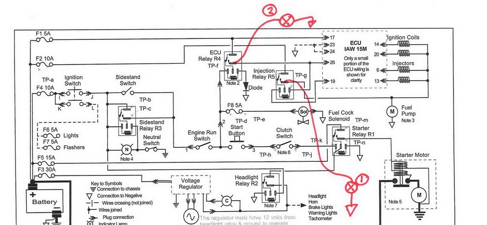
You may have a bad regulator, heres a simple test you can do. I have dismantled 3 Ducati regulators, the common fault seems to be the diodes come unsoldered, the symptoms are weak charging. It's quite easy to check the diodes because they are wired directly to the yellow and red wires. If you have a multimeter with diode test put Red terminal on each yellow wire, Black terminal on red wire and you should see somewhere between 0.4 - 0.6 Volts. If you don't have the multimeter you can use a battery and ammeter or small lamp the ammeter should indicate or lamp should light up if the diodes are OK. (Battery positive to Yellow wire, Red wire to ammeter (lamp), ammeter (lamp) to battery negative) If you don't get a circuit through one of the diodes or it's erratic charging will be weak. Because the diodes are wired directly to Yellow & Red wires it's possible to hang another diode on the outside in parallel as a temporary fix. I successfully opened up my regulator and soldered the diode back together. Roy Regulator Basic.pdf
-
No you don't have to be crazy but it helps, would you rather be riding a Harley just like everybody and his dog? I'm not sure but I think that hose is just a drain from the frame vent, perhaps you could just do a temporay fix by cutting and jambing a length of tube into it. Some expert please comment. Roy
-
The closest I could find was 4,700 pf 1kV I will try that, I could also put 2 in series if you think that's better Thanks Roy
-
Thanks Raz, I will whip out and get the caps, I assume anything close will do Regards Roy
-
Man it's tough trying to join Cliff's forum, he sent me a link that I tried it tells me I didn't join quick enough. Raz, The kit is going together ok I guess but I am having a bit of trouble identifying a few parts. I think the bill of material needs to be on a different page from artwork because it gets cut off in Nth American printout, our page layout is different I have two things that look like 1/2 watt resistors but very low ohms 1 is Brown Brown Black Silver and measures about 0.3 Ohms the other Brown Black Brown Silver measures about 1.5 Ohms are these the inductors L2, L2a, which is which? Another item looks like a MOV marked E60 075 , I don't see that called out anywhere. Cliff mentioned a couple of high voltage capacitors for Q1/Q2 do you know what value they should be, i will pick some up. Thanks Roy
-
Hi Guys, Just when you thought it was safe I pop up here. I recieved my kit earlier this week and I will likely put it together over the weekend Cliff sent me a file "Sport11Stock.ecu" I take it that's the starting point. I will be running Open Loop, no O2 sensor and no Optimizer hopefully that's OK. If I just load the file I assume it will start, am I right? I will check my TPS setting as I go. I think I will combine my exixting ECU and Power Commander into a box to use as spare. When I remove the pressure sensor I will just simulate the sea-level voltage, that should work. If not the cells are readily available for about US$17 I tracked down the 26 pin Tyco connector but I can't wait to order one so I will just canibalize the original. Is there anything else I have to remove from the original board for re-use? Cheers Roy
-
I take your point, if it an't broke don't fix it! With a somewhat richer mixture it did seem to run cooler, I think I had screwed it up thinking excess fuel consumption = rich mixture. A short run (~6km) with the mixture lean and it smelt really hot, I didn't measure the temperature but now after the same run it's about 120°C Roy
-
Yes, I will do that as soon as I can get a reasonable ride in, please see update in previous post - Roy
-
Congratulations, you must have a nice wife Roy
-
Thinking about the symptoms wouldn't it have to be either the ignition or injectors cutting out intermittently, did you try monitoring voltage with a lamp to make sure it stays on at rthe ECU and injector relay output? Another point you could connect a lamp would be to the positive wire at a coil and ground just in case it's lost somewhere in the loom. I would also connect a multimeter up to the TPS input to the ECU and see if that flickers co-inciding with the pops. Strap the meter to the tank so you can keep an eye on it. I suppose it could also be a fuel delivery issue but I suspect it's got to be related to the ECU or something connected to it. BTW, when you disconnect the PCIII and run off stock ECU the injectors are driven by a different set of transistors, I think the coils are always from ECU
-
I never knew that, I always thought it was running rich, but it makes sense for sure, with the modified exhaust as Tom pointed out it will run lean with the standard ECU Thinking it too rich I leaned the PCIII map out "to use less gas" and it ran hotter I, I should have been going the other way which is counter intuitive. I will try it this week if I get a chance. Thanks Roy Update June 24th 2010 OK, I put the PCIII back on and richened up the mixture across the board After a run of about 6 km I quickly measured the cylinder temperature with one of those point and shoot thermometers pointing at fins just below the plug ~115°C for one cylinder ~120°C for the other, that seems reasonable to me. It wasn't a hot day.
-
Thanks for the response The TPS has been set up according to the experts, 150 mV at fully closed 450 at idle if I recall correctly. Intake has K&N filter but no top cover (elephant trunks). The exhaust is standard crossover but with Mistral carbon fiber mufflers, they look like MG07 used on Griso. I believe the PO had high compression pistons fitted. I do have PCIII but if anything when connected it seems to run hotter still. You gave me an idea, I will measure resistance of head temperature sensor so I can put an actual ° number, do you have a temperature or Ohms in mind? e.g. is 120°C hot? I have orderd a MyECU from Cliff Jefferies and I should have it in a few days, hopefully that will help.
-
My 2001 is using way too much fuel, with the regular ECU it's barely doing 20 miles to the USG on the highway and it runs very hot in city traffic. Is it possible to run hot from being too rich as well as too lean? BTW is there any standard spot for measuring the engine temperature e.g. a point where I could attach a thermocouple and compare to the normal reading.
-
It's amazing how oil travels around on the outside of the engine. I just put a new gasket on the sump and the bike started dripping from the back corner, at least thats what it looked like. Eventually I tracked the leak to the oil pressure gauge which is attached to the left side throttle body, I hadn't touched that
-
On further thought. If you suspect it's electrical get a small lamp and thread it through the hole in your brake lever. One wire goes to ground and the other to one of the points I indicate, just jamb it in the socket along with the relay or wrap around the pin. As you are riding this allows you to monitor the voltage at the test point, if the bike starts playing up and the light's flickering it tells you there's a problem before that point, if it's not flickering you can cross that off your list and try a different point. I like to use an LED for this because they are much more visual than an incandescent or a multimeter for that matter. I carry one on the bike as a simple troubleshooting tool. If you don't have a 12V LED just make one using any LED and a 1K resistor. Have you ruled out loose connection in the relay bases? Good Luck Roy

-
Sorry to hear it, sounds like my bike was a week or two back I was having battery problems, battery would drop to 10V, tacho would cut out. I think the voltage dropped so low the injectors would fail to open occasionaly or If you have a Power Commander try removing it, that gives a different set of injector drivers. (mine cuts out on one cylinder at times) or Try my intermittent fault detector to see if you are loosing power at some critical point, this will drop out if you loose power e.g. to the ECU for even a split second. Just use a spare relay. Connect it on to a point you suspect, next time it misses if the relay is still energised you can rule out that point and move to another. Hope this helps Roy Troubleshooting Tips.pdf
-
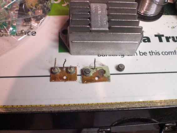
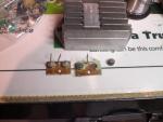
Another picture showing the diode removed alongside a good pair. It is possible to clean up and solder the others back together, I did that with the one on my bike, so far it's hanging together touch wood However this is my project - to replace the original components rated at about 20 Amps with 50 Amp units, a full bridge rectifier and single SCR
-
Mine was installed by PO it's kind of attached to the left hand throttle body, visible when you glance down
-
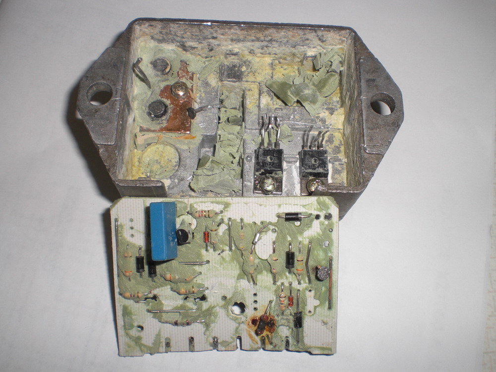
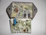
So far I have only pulled 3 apart so I can hardly point to anything but in 2 cases the diodes had come unsoldered and were arcing. This is easy to test for because the diodes are connected between each yellow wire and the red. In fact if you tested and found one open it would be possible to just dig out the corner, cut through the circuit board and repair/replace or simply hang another diode yellow to red on the outside. In the picture you will see what I mean (upper left side of case / right hand side of inverted circuit board) the leads have melted off and the diodes are black from arcing. What looks like a tack laying across the edge of the copper part is the lead that melted off the top diode. The lead from the bottom diode is still attached to the circuit board, RH side 1/2 way down. Actually this regulator is quite repairable, the leads can be soldered back and a couple of cheap components replaced (I destroyed a few getting it apart). The two black semiconductors screwed into the case are the SCRs which are ok. It also has a burnt resistor on the circuit indicating a short circuit in the charge light lampholder but that didn't stop it working
-
My oil light came on the other day, I have changed all the lamps to LEDs It turns out I had washed it a couple of days before and the leakage current was enough to turn the LED on, once the bike heated up and dried out the lamp went off. I have a pressure gauge so it didn't worry me too much. Just thought I would mention it in case others are using LEDs also.
-
Woa! there, what a cool site
-
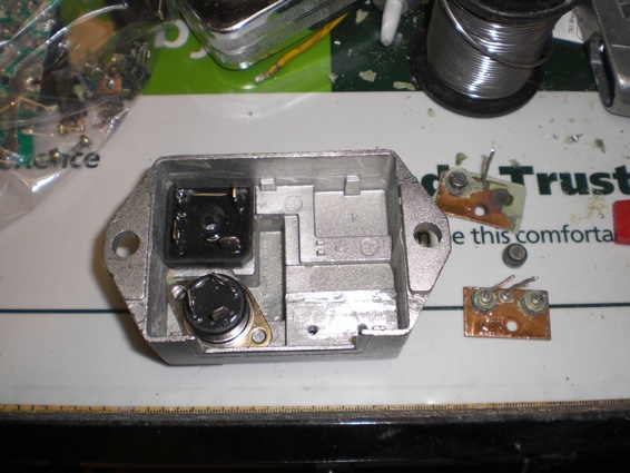
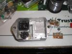
Hi, I have pulled a couple of old regulators apart now, it's not that hard, you just need to be a bit carefull removing the circuit board so as not to damage some expensive parts. If anyones interested I gan do a blow by blow proceedure. Roy
-
Perhaps Ghezzi & Brian is just the name of the shop/dyno outfit that tuned the bike, I think the ECU is thye same as mine.
-
Then how about MyECU, I believe it fits into the original housing
-
I have a Power Commander that is faulty, came with the bike so I don't know how old it is but one of the serial interface variety, runs fine for about an hour then suddenly cuts out on one cylinder. My ECU also has some issues. it starts to run ragged after a while as well, so what am I to do? I could replace the ECU and be back to square 1, stuck with a black box and no way of self tuning. If I stick with the power commander I either have to repair or replace, then I'm stuck with this awkward object taking up valuable space under the seat. The Power Commander only takes over the Injectors, the ECU is still driving the spark etc. What if that gives out on me. or I can replace both faulty objects in one fell swoop for a less than the cost of a Power Commander. I know the idea of putting together a kit is a bit daunting for some but it doesn't frighten me, besides they are available made up. I will probably never dyno the bike, as long as I can get it to run half decent on a regular basis I will be more than happy. I think most of all what I like about the MyECU is Cliff's willingness to share the secrets of his little box of tricks. I should also add I like the idea of building something for the bike. Perhaps I am making a big mistake, only time will tell.