Kiwi_Roy
-
Posts
2,378 -
Joined
-
Last visited
-
Days Won
62
Content Type
Profiles
Forums
Events
Gallery
Community Map
Everything posted by Kiwi_Roy
-
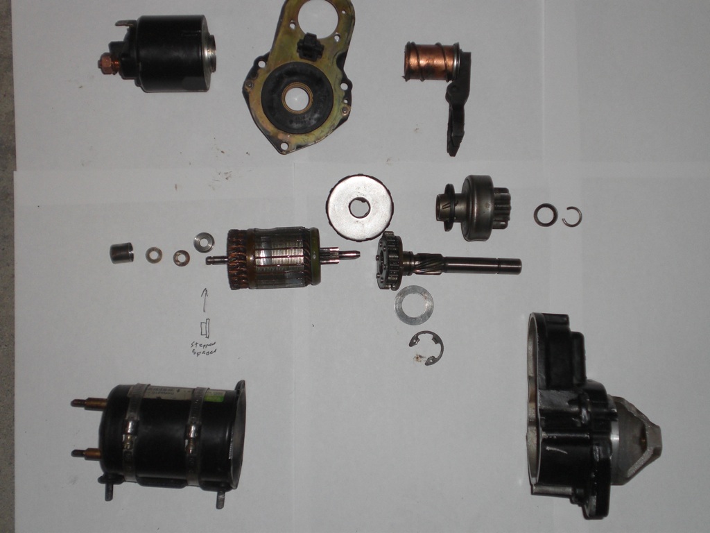
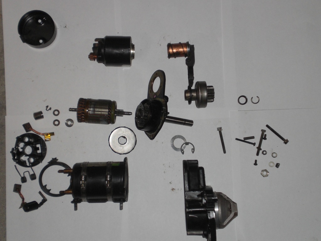
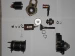
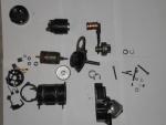
Wow that's quite a task flipping the rotation, the slip clutch would have been wrong too, I must admit I pulled it apart far more than I needed to, I'm crazy that way. Another shot of the main components.
-
I had a few hours to spare so I thought I would overhaul the starter motor. While I was about it I took some measurements to confirm the solenoid wiring. As my bike has done about 80,000 km (only 10,000 are mine) I thought the starter might need some new parts but the brushes still have plenty of length and the bushes are fine so I just stripped it and cleaned everything. Perhaps the previous owner replaced it at some time but he never mentioned it. Starter Circuit Rev 1.pdf Here are the parts laid out It's very difficult to remove the wire clip (on right side of photo) that holds the gear and clutch in place, and even more so to get it back under the cup washer, you might want to skip that part The main solenoid contact on my starter is sealed out of sight inside the solenoid, I decided to leave well enough alone. Once in a while the starter may fail to engage perhaps the teeth clash or something causing the contacts not to make and the 15 Amp fuse to blow, I don't think this is a big deal if it sounds like this is happening just release the start button and give it another shot. If you need to replace any of the phosphor bronze bushes a trick to lube these is to put it on your finger tip, pour in a little oil then close the top with your thumb and squeeze, you will see the oil seep out through the pores in the metal. I'm never sure if I should oil the point where the engagement gear slides along the shaft or leave it dry, I have seen them stick at times when the oil goes like chewing gum. I used a little engine oil in this case because the starter is so easy to remove. Fresh grease in the planetary gearbox sure quietens it down.
-
I will show you my lights if you will show me My ECU
-
Guzzi Wiring July 2010.pdf The Injectors, Ignition and Fuel pump are all powered by Relay 5. It poweres the pump from Fuse 2 see attached. Relay 5 coil is powered by Fuse 1, through relay 4 the main supply for the ECU. The bike will crank over still because the cranking voltage comes from Fuse 4 & Fuse 5 If it's not the fuses it can be the relays or relay base contacts not making properly. If you don't hear the pump priming and it still cranks I suspect F1 or F2 Note the Diode in the coil circuit of Relay 4, that protects the ECU if you accidentaly put the battery in backwards.
-
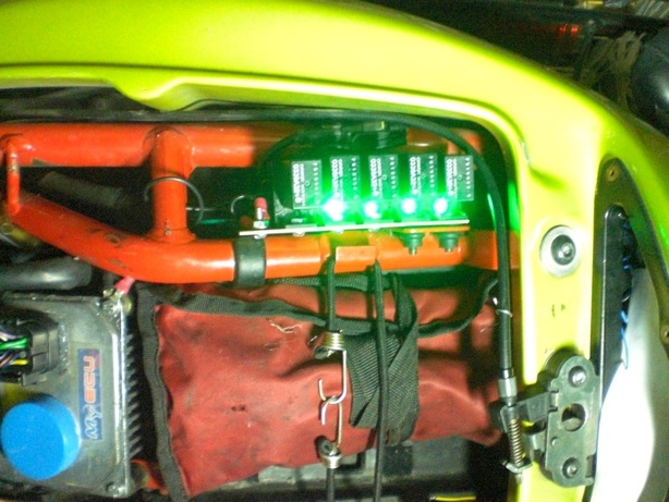
It's a bit slow around here so I will go over my relay upgrade. I removed the relay bases then attached a resistor and LED to each of the 87 contacts. The 87 contact only has power if the relay is energized and the contact is closed. Now I can tell as a glance if one of the relays are out of order. Normally when you turn the key on relays R2, R3 & R4 power up then a split second later R5 picks up for a couple of seconds (primes Pump) Press Start R1 picks up R2 drops out, and R5 picks up When running R2, R3, R4 & R5 are on. Sure beats blindly shuffling relays. Relay Base LEDs.pdf While you are about it, a good time to check the other relay connectors for tightness Relay Base Repair.pdf Enjoy the light show

-
When I replaced my Spark in my 2001 the dealer said it was the original The first Yuasa lasted Roy
-
I thought about using a tiny drop of locktite on the outer thread but didn't in the end, however I was careful to make sure the bolt I used in that hole was not stainless.
-
The video does a good job of showing how simple it is. The tricky part is to get the drill nice and square with the head, it would be very easy to mess up, if I do any others I will make some sort of mandrel or at least mount a square under an adjacent bolt as a guide. I noticed at least one other screw hole with a hellicoil insert, the PO must have stripped a few, I read somewhere that the socket head screws make it too easy to over tighten. Thanks for all the good advice. Roy
-
Yes, I was quoted less than $40 for genuine hellicoil 6mm kit c/w tap. It seems they stock a seperate kit for each size which is good since most on the Guzzi are 6mm Thanks for all your help Update: I picked up a kit today it comes with a special tap, an insertion tool, Insertion guide instructions and 12 stainless steel inserts, just enough change out of $50 for a coffee and a bagel. Actually Lordco list price is $74.47 but they sold it to me for $37 + tax $41.44 The little inserts have a tang that engages with the insert tool, apparently you can snap this off once it's installed. What doesn't come with the kit is 1/4 drill and a punch for snapping the tang off but no problem there, just need a piece of rod with a square end Roy
-
That's what I thought at first, I measured the hellicoil and it's just under 8mm diameter but if I look for a suitable tap the 8mm seem to be all 1.5mm thread pitch, that would force the 6mm to be the same, not 1mm. The 7 mm tap has 1mm pitch Perhaps I need to find a local distrubutor with the correct tap. Update I just got off the phone with a local autoparts store, they sell the kit c/w special tap, one coil size per kit, I'm sure it's cheaper south of 49° but it's worth $40 to get it fixed and 6mm is such a common size on the bike it should come in handy. I gather that the hellicoil fix makes it stronger than original which makes sense. Thanks Roy
-
One of the 6mm x 1mm pitch screws holding the rocker cover on stripped the thread and fell out. I have always been aware of hellicoils but never used one. The PO included 2 or 3 with the spare parts. Can I use a 7mm x 1mm tap or do I have to buy a special tap? Thanks Roy
-
Reading through your symptoms again reminds me of the way my bike behaved with a dirty ignition switch contact. The coils and injectors have a high inrush current, any resistance there will effect their operation. A while back I suggested putting a small 12V LED in the hole in the brake lever pivot and run a wire to various parts of the electrics under the seat. LEDs work better than incandescent because the light output responds instantly to change in voltage, it will show at a glance if you have an intermittent connection. If you don't have a 12V make your own with a superbright LED and a 1K resistor. I may be barking up the wrong tree but at least you can check the electrics off the list. A point I would connect to The Positive wire at the coil - that will check you have a steady voltage at the ECU proving out your relays etc. I would also connect a multimeter across the battery and strap it to your tank. Kangaroo hopping can be a symptom of over - voltage, don't ask me how I know. If you haven't already done so provide a good ground strap to your regulator, don't rely on the poor grounding from a couple of screws, it might have been fine when the bike was new and shinny but aluminium to steel in a wet location Here's an easy way to check your ignition switch from under the seat, see Note 4 Test Point Layout.pdf BTW, do you still have the electric petcock? Hope I have given you something to think about. Roy
-
Thanks for the heads-up, i will check mine tonight Update, Sure enough, the one on my triple clamp was ready to let go. The foam had broken down The two on the pork chops seem to be well stuck on. Thanks Docc, I owe you one.
-
Re the Brake switch. Check also that there is a small plastic rod about the same diameter as a bic ballpoint button inside the brake lever, that may have dropped out. The switches are a standard pattern, Cherry is a brand that may be available, if you can't find one PM me. It's also possible your relay bases may be the problem, with frequent swapping the connector may have spread apart, putting a new relay in it might be making contact again, heres how you can easily tighten them up Relay Base Repair.pdf I added LEDs to my relay bases so I can tell at a glance which are made. Connected to the 87 contact the LED checks both the coil is energised and the contact is closed. Relay Base LEDs.pdf The relays are easy to test, first of all you should measure something like 100 - 120 Ohms from one small pin (85) to the other (86) (the two outside ones), if you don't see that the coils toast. you should see zero Ohms from the flat horizontal (30) to the 3rd small pin (87A) and an open circuit from 30 to the other large pin (87). When you energize the coil with 12 V (30) to (87A) becomes open while (30) to (87) becomes zero. When buying replacement relays buy all 5 pin variety.

-
Not here because I'm afraid of using up the 200K I'm allowed, but I do have a couple pics up here: http://splicer.com/2011/01/19/taking-black-racer-remote-office So... it sounds as though adjusting the idle is more complicated than I thought. I'm completely unfamiliar with both VDST and TwinMax. But thank you! You've given me leads for researching. Nice looking bike, I notice that the air filter pods have been extended, I did that with my V11 Sport using the rubber pieces that connected to the original air box, it made the world of difference to the torque over just fixing the pods directly on the throttle body. I believe the TwinMax is two vacuum gauges, heres a balance tool you can make yourself for a few dollars, more accurate than using two gauges but not as convenient. Carb Sync Tool.pdf Near the cylinder head you will see a 6mm screw, thats where it attaches, I hunted all over looking for barb fittings then I realized that 6mm grease nipples were perfect, you just have to remove the ball and spring by grinding a little off the back. You also need to hold the plastic tube on with a wire twist or ty-wrap or it falls off when hot. Use 30w engine oil and you don't need to apply a damper block, suck it out of the bottle, I made mine just long enough so I could stand it on the ground leaning on the seat.
-
Excelent job Tom, I pried my speedo apart last month with a screwdriver and a pair of sidecuters to bend back the crimp, your special pliers made a much neater job. The odometer on mine had jambed up stripping the worm on the plastic drive shaft. I pulled the tumblers apart and swapped them around from left to right so the worn parts are now on the left where they get little use. Hopefully the shaft has enough grip left to turn the smaller trip odo. Update, I decided to do my tacho as well, made the special tools to yur specification, workrd better but still marred the ring somewhat. It really needs a solid support ring just larger than the bezzel with a pivoted lever to turn back the crimp
-
Buzzard, You are right on about the ground causing bad running, a good solid ground strap to the regulator is a must IMHO. I drilled a hole in one of the fins and ran a strap from there back to a timing cover bolt. I don't think everyone realizes that all the charging flows back through the ground. The regulator doesn't regulate the battery voltage, it actually regulates the Voltage between it's black wire and it's case so if you have a high resistance from the case to the bikes chassis whatever Voltage drops is added to the battery. e.g. if the regulator is set at 14.5 and you are loosing 1 Volt between the case and chassis the battery will be charged to 15.5 I know for a fact that if the Voltage on the battery goes too high as you accelerate the bike cuts out as the revs build up causing it to leap frog (bucking) I have a theory that bad grounding is what causes the regulators to fail, the excess Voltage causes too much current for the regulator diodes and the leads melt off, I have found this to be the case in the three I pulled apart. Another thing that causes bad low speed running is a bad contact in the ignition switch, after a few years the grease goes stiff holding the contacts apart. I haven't quite figured out how it causes the bad running since the supply to the ECU goes through relays but for sure it did on mine and also another owner I know. Bad contact between relays 4 & 5 and their bases is also also a problem, the injectors and ignition coils have an inrush of ~20 Amps, any little resistance in that circuit must play havoc. So ground your regulator, clean your ignition switch and tighten up your relay bases ready for spring. Roy Regulator Basic R1.pdf
-
While it's always nice to have the right tool for the job sometimes you have to improvise. All you need is something to drive them in without cutting the plastic or scratching the surface. I was just looking at a post for driving the seals on a Goldwing using about 3 ft of PVC pipe. To protect inner surface of the seals from the sharp step on the inner tube just a turn of plastic tape. I don't profess to know what I'm talking about, but I just noticed a pool of oil by the front tire of my GW so I'm getting ready for the project. I had my V11 Sport forks apart without any special tools at all. Good Luck Roy
-
As I said, if the pressure is different I think the fuel mixture will be different but it's not that sensitive, to double the flow you have to square the pressure. I looked in the workshop manual sure enough the regulator is set at 3 bar(g) and the pump relieves at 5 a difference of 2 so even if you pinch the return right off you will not get a lot more fuel, 25% more worst case. if you added a small pressure gauge you could set it close to 3 Bar by pinching the hose. It won't matter if you are just trying to run the motor, not tune it. Thanks Roy
-
When I was an apprentice electrician we used to fix a lot of conventional starters, series motor type. A lot of the times the field insulation was broken down and it was shorting to the frame. We would re-tape the fields. The Valeo on my Guzzi was the first permanent magnet starter i had seen. Simpler in one way without the series field but more complicated with the gearbox. Good point about the small battery the shunt motor (permanent magnet) draws less current once it gets spinning but then again it won't spin as fast. Regards Roy
-
All kinds of good information on the Airhead site if you click on the links Here's an article on changing from Valeo to Bosch. http://www.airheads.org/content/view/307/98/ Another good site http://www.dansmc.com/electric_starters.htm I think the Bosch starters are a conventional series wound motor. Series wound motors develop more torque and speed so they can do away with the reduction box Shunt wound and permanent magnet motors have the same characteristics, low top speed whereas a series motor will wind right up if the torque is low enough so they were the main choice for traction applications, think diesel electric trains. Is spitting the magnets a common problem with Guzzis or is it more common with BMW because of the hot starter location? Roy
-
Just a suggestion, if you have the gauge type throttle balance tool you could strap it to the bars and check the balance while riding under different load conditions.
-
Here's a sketch. Provided the power is making it through the contactor the current through the starter relay is less than 10 amps but if it fails to get through as far as the brush the heavy coil will draw too much current and the fuse will pop in no time, see the third sketch. Please note: my sketch may not be 100% correct, I don't have a manual for the starter, this is my best guess from the readings I took and pulling mine apart, so it's close. BTW I was taught not to lubricate the starter sliding parts, just leave them dry or use CRC or something that will not become sticky after an few months, grease in the gearbox is fine of course. I also found this very good article on the Beamer site http://www.airheads.org/content/view/210/98/ I was unable to find a schematic, so I'm going with my sketch for now Starter.pdf
-
It's not quite clear how you keep the regulator in circuit. The regulator on my V11 is screwed into the bottom of the tank, if you bypass it the fuel will be at a different pressure and the mixture will be wrong. Please clarify Thanks Roy
-
The solenoid inside the starter has two coils. one has a resistance of only 0.3 Ohms (12/.3 = 40 Amps) but that's only for the split second that it takes for the gears to engage then the current drops to about 6 Amps. Your symptoms to me sound like either the internal contacts aren't making or there's a bad connection on the main wire from the battery to the starter. I would check the battery connection first, remove the wires and scrape the lead terminal until it shows nice clean metal then coat the connection with petroleum jelly aka vaseline. Do the same with the main connection to starter. If that doesn't fix it something must be preventing the internal contacts from closing. When you press the start button the start relay energizes the heavy winding (0.3 Ohm) in series with the starter armature. This heavy current creates a strong magnetic field to pull the starter gear into engagement. Once engaged the main solenoid contacts now supply +12 Volts to the armature and the negative end of the heavy coil. Since both ends of the heavy coil are now at 12 Volts it no longer pulls 40 amps through the starter relay and it's 15 amp fuse F5. The solenoid is held in place by a lighter coil which only draws 6 amps (less magnetic field is required to hold the gear in place). If the contacts in the solenoid are unable to supply 12 Volts to the armature the heavy coil continues to pull high current through the starter relay and the fuse pops. Sorry if my explanation is not very clear, I can post a sketch if that helps. BTW the fact that your fuse pops tells me the brushes are connecting with the armature. The relays are rated about 60 amps inrush so the initial surge is OK See note 6 of attached Hope this helps Roy Test Point Layout.pdf