Leaderboard


Popular Content
Showing content with the highest reputation on 06/05/2025 in Posts
-
Since I needed to drill out the piece of the nut driven down into a keyway to lock it, I kept going and stitch drilled the nut so I could split it. Tightening a new nut meant that I had to get a better way, so I made wood clamping blocks to grip the pinion in a vice. I should have made the clamps first.3 points
-
You can see seal ID running face in the pic. I could send you the socket to undo the bearing retainer nut if you didn't live on the other side of the planet...


 3 points
 -
Plowing through the parts fisches at Harpers, the first thing I could find that takes a different slave arrangement from this V11 is the 2007 8v Griso. I wonder...if I could bore the case and use the Griso bearing bits and pushrod. I have to inventory everything now that I have the transmission in hand, I have the throwout bearing and pushrod but haven't seen the bearing/pushrod hat. Meh. Looks like everything is very different, and the correct slave is only $90.3 points
-
I'm having a bit of a nostalgia wave at the moment, which is why I came up with these. I'm pretty sure @Lucky Phil knows both of these roads, but as a responsible citizen he has most certainly never ridden along either one at more than the legal speed limit. This one was a regular destination as part of a day ride. It was an easy ride out from where I lived, and further outwards there are some more "attractive" roads. Incidentally, the bush looks a bit weird because a devastating fire went through there in the early 2000 years. That is what a Eucalyptus forest looks like after a fire, and it looks like it is coming back pretty well. Anyway, this is the road on which I learned that the rule of thumb that you can double the recommended speed limit and add ten percent doesn't always apply. That road is here: https://www.openstreetmap.org/directions?engine=fossgis_osrm_car&route=-37.6027182%2C145.272874%3B-37.5327424%2C145.341131#map=13/-37.56778/145.30706 Then there is this: That is here: https://www.openstreetmap.org/directions?engine=graphhopper_car&route=-37.80205%2C145.00992%3B-37.78815%2C145.02511#map=14/-37.79469/145.02357 Of course I never, ever went there and engaged in antisocial activities in the middle of town. Well, not very often. Definitely not more than once a week. Depending on which week it was.2 points
-
Nice Mick. The Kinglake road St Andrews end is only 10 minutes from my place so I know the road pretty well. I've been along the YB quite a few times as well. It's amazing to think the YB is almost literally only a stones throw from the city centre. Sound like you need a decent holiday back home Mick Phil2 points
-
I would agree with Phil. Can you install the new rubber manifold boots without removing other parts? Sure. But it is going to be hard, mainly because of the awkward angle of how the throttlebodies attach to the heads. Sometimes it is easier to take something further apart to put it back together. But to each their own. I would put in a little extra work to take things further apart to make putting everything back together easier.2 points
-
Thanks for all the replies, just to be sure I ordered the seal already. I think indeed cleaning it and then driving a little bit to be sure is a good plan! I will start extracting the rear drive this weekend and hopefully find the problem. I was hoping that the pinion would not have to be extracted as I don't have the tool. On my V50 it was all a bit easier I will keep you all posted on the progress2 points
-
I also wondered about that washer.2 points
-
I don’t think that the suggestion was that you were trying to be deceptive, simply that the information you were imparting was wrong and not relevant. For people seeking answers to specific questions it is important to not muddy the waters with irrelevant information and the fact is that a drain plug falling out has precisely nothing to do with a leaking pinion seal. Oh, and a quick edit regarding your edit. The sealing principle on your Quota’s bevelbox and that of a V11 are entirely different! The pinion on the Quota box is unsealed. All the O-rings on the carrier do is prevent oil leaking out between the pinion carrier flange and the swingarm and box casting. The front bearings are unsealed and in fact the box breathes into the swingarm! The V11 box is sealed and breathes via the breathe installed in the case. WRT the pinion seal on the V11 box I’ll have to go on memory as I haven’t done one for fifteen or more years but, like so many other Guzzi final drives, the construction is a bit, errr, unconventional! I do believe that the ring nut as it is called needs to be removed to extract the seal, (I’m happy to be corrected if I’m wrong.) but the reason the seal might leak should be examined as well. The V11 pinion support assembly is all a bit odd. Unlike most pinion mounts the shaft of the pinion is not supported by opposed tapered roller bearings. The advantage of that *Conventional* set up is that both the support and end thrust on the pinion shaft are taken by the opposing bearings. With the V11 pinion though the forces are dealt with separately. The rotational load is taken by a substantial roller bearing but the end thrust is taken by a large caged ball race. These are both ‘Contained’ in one large outer race BUT the outer race of the ball part of the bearing is split and the whole lot is clamped together by the ‘Ring nut’ which contains the seal and the seal runs on a spacer between the centre race of the queer two part bearing and the pinion lock nut. Now also for the first time in a Guzzi bevelbox the pinion has a support bearing inboard of the head of the pinion. It’s a small needle roller similar to the pilot bearing for a gearbox input shaft in some car flywheels. One unfortunate thing though is that it tends to not get oiled very well due to its location and this can lead to brinneling of the outer race and premature failure. If this happens and play/clearance becomes excessive it will lead to increased loading on the two components of the two part shaft support bearing. Now being a Guzzi and therefore being built like a brick shithouse this doesn’t often seem to cause problems but if for instance the box is run low on oil or worse yet gets water in it brinneling and wear can occur in the support bearings and if this happens the pinion shaft can begin to run off its axis. This will have dire consequences for the mesh of the gears and their life but one of the first signs that something is wrong will likely be the pinion input seal blowing and the resultant oil loss. Now I’m not saying that anything like this has happened, just that you should be aware it can. Certainly if my bike had popped it’s front seal I would probably take it upon myself to pull the crownwheel cover plate and examine the teeth of both gears and then while it was off have a really good tug and thrust at the pinion just to see if it had any axial or lateral play. If it does I’d investigate further rather than simply sticking in a new seal and calling it sweet because the new seal likely wouldn’t last very long.2 points
-
People do not consider the ground to be an important part of the circuit.2 points
-
Well thats totally misleading. Different rear drive unit and in your case the drain plug fell out due to poor maintenance practices. This is how rubbish gets propagated on the internet and therefore I'm highlighting it straight away. Phil2 points
-
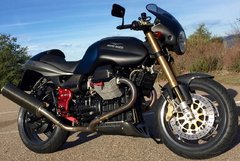
Michael has a very pretty Tenni in at the moment. I think it actually belongs to a member here, not sure though. Anyway it came to have a RAM clutch installed among other things. I can’t remember how far it’s travelled, certainly not very far but have a squizz at the flywheel! The first pic is just to show off Michael’s spiffy new crane! Makes working on things like this a doddle! This is the flywheel! As you can see it’s a real doozy of a crack! Tick-Tock Motherf*cker! Oh, and Michael used the board for advice on how to yank the engine out of the front. I’ve never done it that way so couldn’t advise so thanks for that V11 people

 1 point
 -
Yeah, that's on the plan.1 point
-
Thanks for that. I have a good friend who lives in Carlton, but I don't know for sure if he can put us up. I'll get in touch if needs be.1 point
-
Yea I was thinking of a wooden clamp in the vice for the pinion drive. I'll set it up in the mill and use a 4mm end mill to cut out the staking on the old nut and replace it with a newy. Phil1 point
-
Funny that, because, being a circuit, everything in it is equally important. Otherwise, the circuit wouldn't be a circuit, but rather maybe a semi-circle or a drag-strip or something.1 point
-
They have become rather expensive! I remember being surprised by how cheap this part was (back in the day 🤪)1 point
-
Ooooh! Much nicer tool than mine for the ‘Ring Nut’! Will you make one for me mister? Please! Pretty please! As for holding the pinion shaft? From memory I had a buggered Uni-joint/driveshaft from my Convert which had the same splineform that I stuck in the vice, bunged the pinion in and cranked it up with a FB spanner. Thats my memory. Certainly the CARC bikes use the same splineform and size so finding a buggered shaft and getting one of the yokes would work. Actually I’ve got a horrible, damaged, shaft from a Cali 1400 on the verandah, (Who doesn’t?) I could chop that in two and that would make two holding tools. One’s yours if you want Phil. Anybody else? First come first served. One of the yokes will need dressing up with a file due to the crash the bike it came from burring the end of the front yoke as the whole motive unit moved forward in the frame, (Rubber mounted engine in the 1400 and this bike had its front end taken off in an accident and came to a ‘Sudden Halt!)1 point
-
How did you hold the assembly while you undid the hex nut? Phil1 point
-
I had a quick look at the one you gave me in bits and the problem is the nut pulls up against the seal inner running sleeve and the nut is a larger dia than the seal running face. You pull the whole pinion shaft, bearing and seal as a unit with the nut in place if you like. I remember you saying the easiest way to remove the nut is with an windy drill and a cutting disk.1 point
-
I thought it could be plucked out with the old self-tapping screw through the face of the seal trick and a new one slipped over the nut? As I said though I haven’t done one for a very, very long time!1 point
-
The real problem with the input shaft seal is Pete that the pinion nut has to be removed to change it and that's a right bugger as you know. Phil1 point
-
No I assumed you were just firing off a post without considering it would be misleading. Phil1 point
-
Three months (thirteen weeks) out, and Ken (the innkeeper) tells me there are four rooms (of 16) left at The Lodge at Tellico. Of the twenty-one years of this "South'n SpineRaid ", this is our sixteenth at this location. There are "reasons" we keep going back . . . Y'all come, now! Ya hear?1 point
-
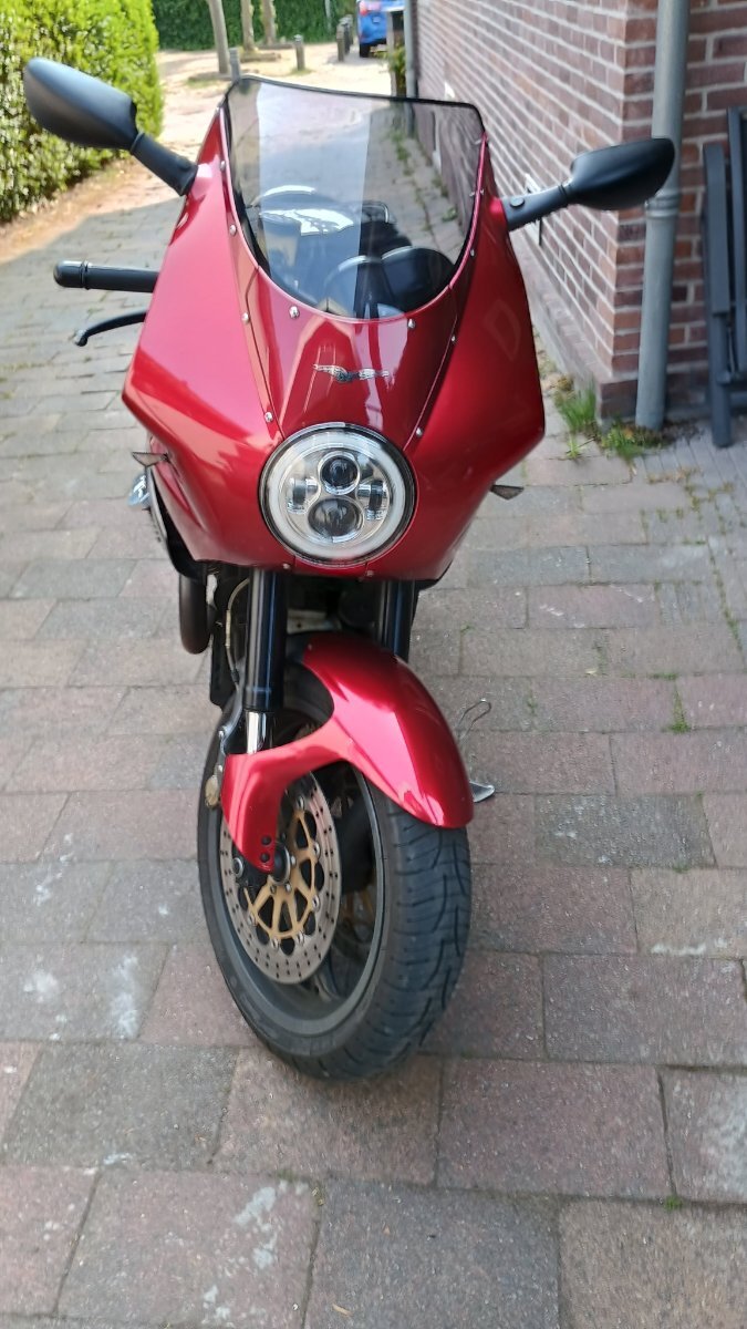
@nielsv11, Once that wet, it can be hard to know where a leak started. Perhaps clean up, apply a "foot powder" and go for a short ride (after ensuring these is enough oil in the box!). The powder will discolor at the source of the leak.1 point
-
I made a mistake as I had two different tabs open. I have edited my post to include all the information I had initially planned to provide. Interesting that you automatically assumed I was purposely trying to be deceptive.1 point
-
I dunno...that's a noise my dog makes.1 point
-
Dunno, maybe not yet and I’m not going to waste time die testing it. It’s buggered. That’s all I need to know.1 point
-
Yes, it's still hard to believe how well it all turned out, but I'm very happy about it!
 1 point
 -
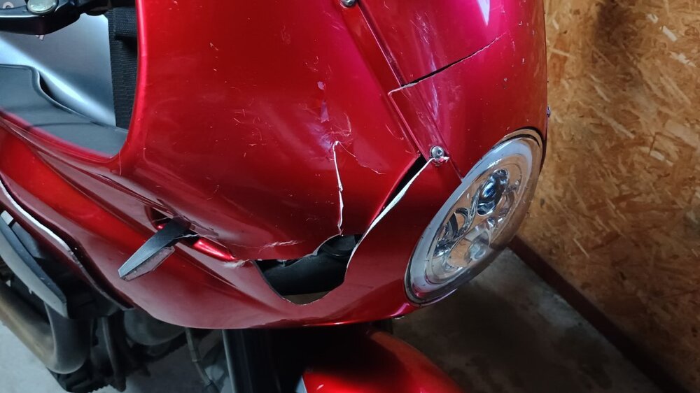
There are four rubber boots in total. Loosen the two rear ones that connect the airbox to the throttle bodies. Then you can push the har plastic tubes back into the airbox, which will give you room to back the throttle bodies away from the heads and remove the broken rubber boot(s). It doesn't sound like any further damage was caused, since the engine was running for quite a while with the broken intake boot. This is a common problem, because those parts wear out from age and vibration. When you put everything back together, put the new boots on the heads, then connect the RH throttle body, then the left. (since the RH cylinder is farther forward, connecting RH first gives you a better angle when you connect the LH throttle body.) Then attach the intake pipes from the airbox and tighten all the clamps.1 point
-
There should be O rings at the T fittings. Your local NAPA should have them. It certainly isn't a picnic taking the injectors off. IIRC, there's a circlip that needs to be removed to remove the T fitting at the injector. If you're going to remove the injector for this, it wouldn't hurt to send them in for cleaning at that point. I sent mine to www.lindertech.com, and I think the total cost with shipping was around $80 for the pair. Did you use fuel injector clamps when replacing the hoses? They don't dig into the hoses like standard hose clamps do. Ken1 point