docc
-
Posts
20,502 -
Joined
-
Last visited
-
Days Won
1,189
Content Type
Profiles
Forums
Events
Gallery
Community Map
Everything posted by docc
-
Seems like a lot of trouble when you can remove the front trim with three fasteners and lift it off along with the "lens" to access the bulbs from the surface. Sure, you could crush them trying to grasp them with a tool, but should be able to gingerly remove and replace them without all that disassembly.
-
Yessir. But, why remove the speedo? No need to get to the warning bulbs, IIRC.
-
They are reversed threaded. But no reason to remove it to get to the warning bulbs?
-
Rosso Mandello has the same frame and subframe configurations as the early RedFrames.
-
With this caution, the bulbs are actually quite easy to access. They can be removed by gently grasping the globe with hemostats (also known by "other " names ). The glass tends to get "zinced" after a while and look black like they are blown, so put 12 v across and see if it lights. Not a bad idea to change them all to "long life" fresh units for a brighter result. Always: a spritz of magical Caig DeOxit® when things go back together . . .
-
About a week out and I see I started the Sport's shakedown three months ago and have ridden it over 2700 miles. About as ready as it can possibly be and properly separated from the Waddington Effect (unwanted outcomes from my messing with it ). I told a buddy that if I didn't saddle up and head out next week she would probably sprout a cortex and leave without me! SpineRaiders are looking to number 10-14 for this S'xteenth South'n. Y'all ride well, ya hear?
-
Makes me wonder if keeping my Sport on the lift in the chock all the time has helped spare my sidestand switch . . .
-
https://www.baxleycompanies.com/
-
So well done, Lucky Phil! Just stellar, your documenting this and sharing. This is exactly the kind of thread that belongs in the "How to . . ." sub-forum. Thanks, again, Lucky Phil!
-
(Idle is kinda low there, bud. CO looks fine.)
-
AFAIK, no US V11 had oxygen sensors. Pretty awesome SooRoo has found this simple change! Something we would have never discovered in places where the V11 has no O2 sensor . . . (off topic, then: biggest two issues I see missing from your list @Tom in Virginia is CO Fuel Trim zero and TPS baseline. Pretty sure those are on for the SpineRaid TechSession!)
-
Curious what’s up with Dietcokeman. Always a bit un-nerving when one of us puts his V11 up for sale....
-
Looks like the seller may be our own @Dietcokeman . . .
-
Relay#3 is the least stressed relay in the stack. It is energized by the Neutral Switch so the bike will start and run with the stand down. In gear, the Run Switch gets power through the Sidestand Switch when the stand is up (no relay). Calling Relay#3 the "sidestand Relay" is a misnomer and source of confusion, IMO. The Neutral Light is lit by the Neutral Switch before the relay, so will be lit even though the relay is absent or may have failed. That your bike will start in gear suggests a stuck Sidestand Switch, its wires crushed together (like under the alternator cover), or (perhaps most likely in your case) some PO decided to defeat the switch and hot wired it (twisted the wires together) upstream from the switch. Follow the wiring upstream from the sidestand and look for an ugly blue box (ScotchLok! ).
-
Yeah, those alternate headlamp harnesses with their own fused power and separate relays for hi- and lo- beam were a way to deal with the overloaded relays early on. My Sport has this system, but no longer used since finding a reliable LED headlamp unit. And High Current micro relays (OMRON G8HE). The very first issue my dealer addressed on my Sport (within a couple months) was to send me a larger relay for the #1 position. Later (~2002), Moto Guzzi changed the wiring harness to power Relay#2 from the Ignition Switch instead (like older Guzzis with "Startus Interuptus"®).
-
Yep, the green/white power input to Relay#2 is what would come from the 5th pin of Relay#1. Not many micro relays in the world have the rated capacity to handle that current through the weaker NC contact, but your G8HE OMRON will do it. Once that ScotchLok is off, try to make sure it has not damaged the power wire to Relay#1. By design, they cut into the strands.
-
So, that discussion is about using separate relays and direct wiring for the headlights, but not about the existing relays and how they are wired in the factory harness. That wiring actually bypasses both Relay#1/Start Relay and Relay#2/"Headlamp" Relay to supply power through a dedicated headlamp harness from the battery.
-
Well, you will need to replace the connector that fits into the relay base. Unless it is still part of the wire to Relay2?
-
On the early V11 Sports, the entire load on Relay#2 (including the headlight) is fed through the weaker NC contact of Relay#1. Running a High Current OMRON has not always been a known solution, so these folks just bypassed that function by combining the power to both relays. Relay #1 will no longer be stressed on that contact since it is bypassed. Sure the LED draws less. I am not sure if it is bad for, say, the tachometer to experience that drain from cranking then some kind of inrush current. Or if that inrush current is any higher than the NC contact reconnecting in the unaltered design. Someone else should comment on those ScotchLok connections. I've always heard they are frowned upon. If you were to leave it wired that way, I would think a more positive connection would be desirable.
-
There it is. Some PO, or their "technician" modified the wiring by using that nasty ScotchLok to defeat the 5th pin "load shedding" function and simply connect the power input to Relay#1 with the power input to Relay#2.
-
Or perhaps, when you investigate the relay bases to perform the Kiwi_Roy tightening procedure, you will find someone has pulled that 5th connector from Relay#1 and wired it hot to where it powers Relay#2. Essentially eliminating the weak NC contact/ 5th pin of Relay#1, but leaves all of that load (especially the headlight) on while cranking.
-
How odd! Relay#1 is the Start Relay. When the NO (Normally Open) contact is pulled in with the Start Button, power is sent to the Starter Solenoid. When the contact flips back to the NC (Normally Closed/ "5th") contact, power is directed to Relay #2 for headlights/brake(stop) light/tachometer/warning indicator lights/voltage reference. This effectively defeats all of that power draw during cranking. Does your headlight go out while cranking?
-
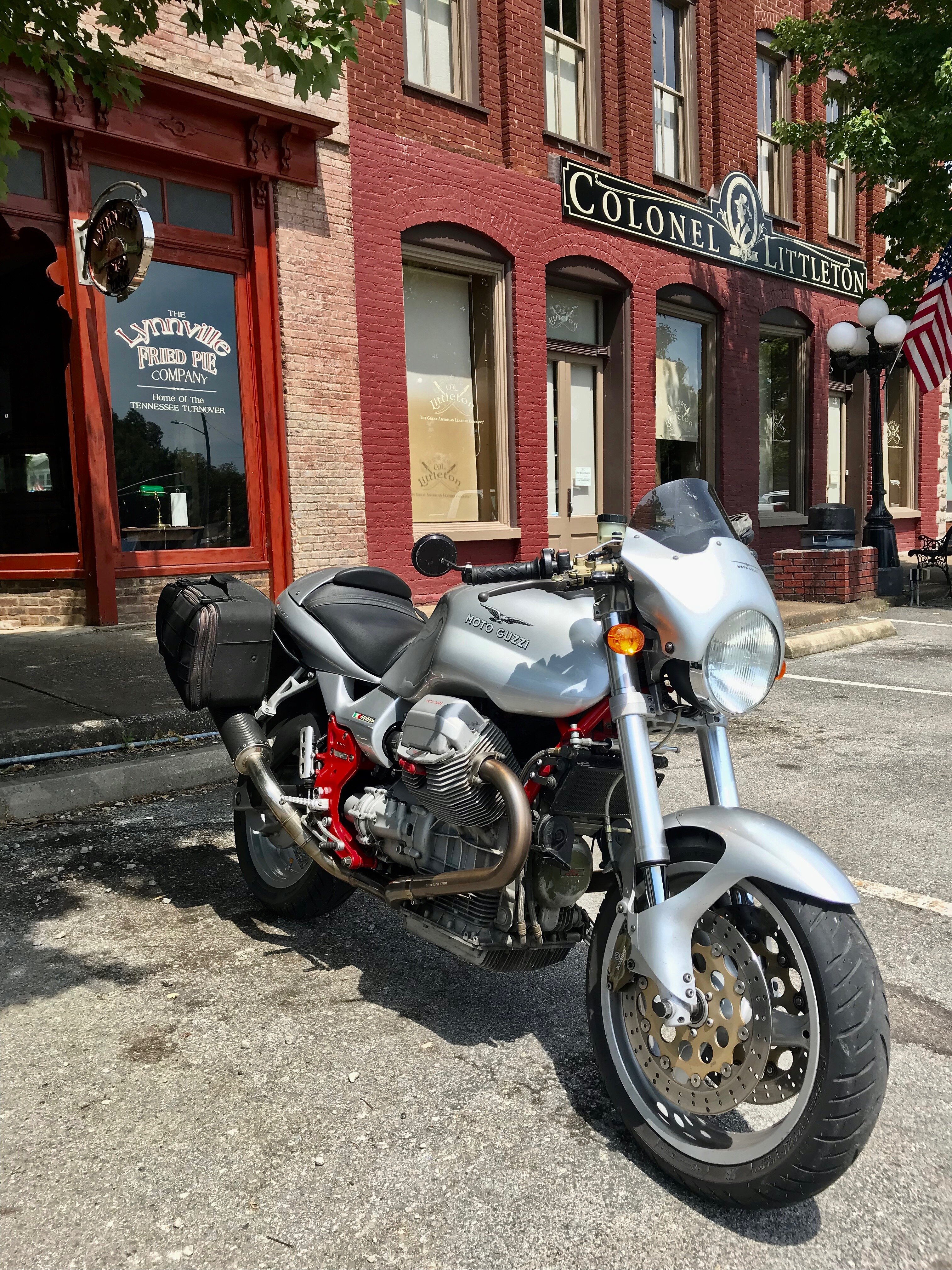
I found this in "Post a pic of your V11", but it does not show the wheels well and has a funky aspect ratio . . @Mikko, happy to hear all the parts are available to mount the wheel. Now to hunt up the front!
-
Yes, this failure is difficult to see without exposing the wiring: