docc
-
Posts
20,496 -
Joined
-
Last visited
-
Days Won
1,189
Content Type
Profiles
Forums
Events
Gallery
Community Map
Everything posted by docc
-
Aaaaaah! "Champagne!" That explains it!
-

My Long Time Dream Machine, the Jota
docc replied to JBBenson's topic in Special place for banter and conversation
Ha, so . . . "lounge bikes" are all good if you can roll up some serious time on them . . . l love the "lounge room" moniker. Not sure why . . . -
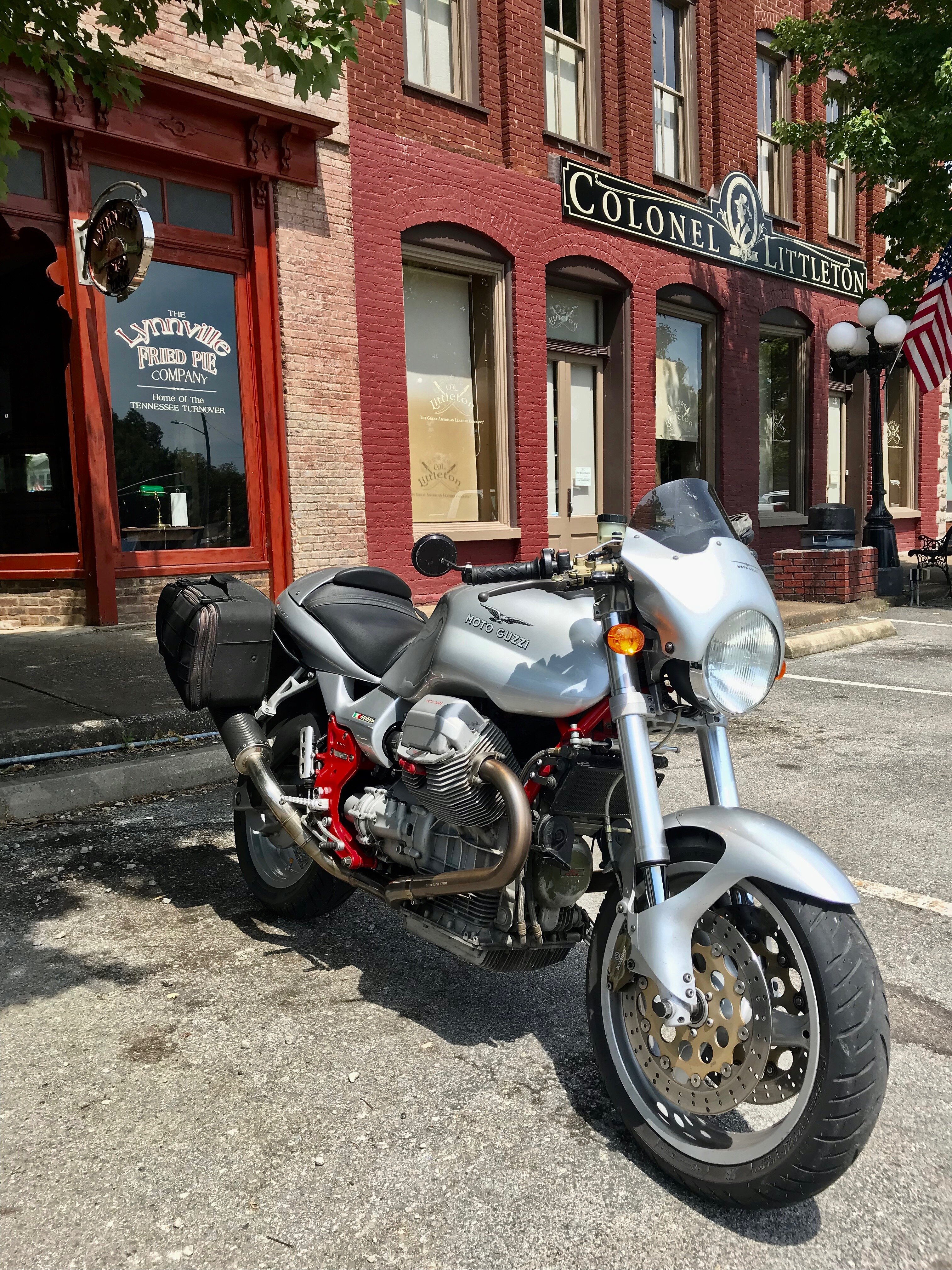
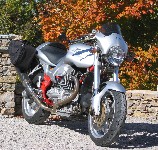
From the album: docc's sport
http://www.v11lemans.com/forums/index.php?showtopic=19844&p=218448 -
Nobleswood, I moved the topic here from "How to . . . " before seeing it is about the Griso. We will likely do better to have it in "New Models." Recent posts about an '09 Stelvio "Quatro Valvole" (per cylinder) led another member to a "roller kit" upgrade. 2013 Griso should already be addressed? So, it can't be the tappets? "Tap-Tap" tappets?
-
I'm thinking your "knowledge of metal strengths/fatigues" has just increased exponentially! Obviously, those ends are not at all up to the task! :o
-
My Long Time Dream Machine, the Jota
docc replied to JBBenson's topic in Special place for banter and conversation
You say "one for the lounge room" like it's a bad thing . . . -
I had trouble getting a connection yesterday and remembered you have to select your model of Guzzi from the preferences first.
-
Tinus, This is very interesting. We had always thought the RM frame and the early RedFrames were identical except for color What is the wheelbase of the Rosso Mandello?
-
Goofman just checked in. Perfect 1200 rpm idle, Sport running great! Bravo! Here's to this community! Pete - you da man, man!
-
Last year's TechSession is going to be hard to top!
-
Glad the Stelvio is back in fine fettle! Guzzidiag, and my mercury sticks, served us well. Goofman is on his way back to the city. Seems the several stops we made the 1200SPORT was idling nicely. It was brilliant, really, to simply set the Throttle Angle back to 4.6º, it only bumped to 4.8º when it started, so we attempted no Nasty Kludge. Waiting to hear back (this evening) how it behaves after an hour on the road. Hey, Pete . . . thanks, again, so very much for the assistance and the education. It is revealing to understand that is not an "idle stop screw" but actually the throttle plate screw which is preset. Also, good to know that the air screws are not used the same as a V11. Thanks, Pete!
-
Of course!
-
Goofman's bringing it to The Fountain Oaks Perverse Testing Facility this afternoon and we'll see what there is to see getting the throttle plates back around. Since we last fettled it, he installed a fresh (much needed) air filter and found one the the throttle intakes a bit unseated. Thanks, again, for the insights and encouragement!
-
Great, thanks czakky! That was my guess but didn't want to force it. Maybe drizzle a little of your favorite CLP into it first?
-
Get'that-get'that-get'that, too!
-
How great is that? This year, you're gonna need a better alibi to skip the South'n Spine Raid . . . http://www.v11lemans.com/forums/index.php?showtopic=19767
-
Perhaps, but it'll provide forum fodder for the foreseeable future. get'it-get'it-get'it-get'it . . .
-
"new bikes" . . . heh!
-
Wait . . is The Sacred Screw on the left throttle stop, or the right?
-
yup, that range should cover it. Leave something back for the various *undiscovered* fun that you will invariably want to have with it . . . (Assuming some previous owner has addressed all and every issue is likely a formula for some disappointment.)
-
I'm glad the SpineFrames are "old enough" now to be on their to-do list.
-
really? I've never seen grips that weren't different sizes. I like pro grips gel, BTW. Takes out that little ticking in the bars. YMMV, of course. Right? Motorcycle grips already are sized for the the throttle tube on the right.