docc
-
Posts
20,498 -
Joined
-
Last visited
-
Days Won
1,189
Content Type
Profiles
Forums
Events
Gallery
Community Map
Everything posted by docc
-
350 watts @ 5000 RPM/ (14V - 25A)
-
@Cash, I can't get that to link. Could you give it a look?
-
I would like to upgrade my H4 without adding a separate driver or fan. Not long ago, a member here posted an H4 LED, but I can't find it. Something like this? http://www.ebay.com/itm/1x-6000K-White-40W-4000LM-Hi-Lo-Motorcycle-Bike-LED-Headlight-H4-HB2-9003-/142078762956?hash=item21148ddfcc:g:i7MAAOSwX9FZGA6r&vxp=mtr Do they get too hot for the early Sport steel bucket?
-
Yep. You could probably fit a tap (petcock) in place of the regulator and use an inline regulator, "T" the lines together and find safe places to put everything being certain not to foul the throttle linkage. The V11 is actually pretty tightly packaged when trying to make changes in systems like electrical and fuel line routing. Having sputtered out of fuel on the V11 (too many times ), you can dismount, and very deeply slosh the fuel from right to left. I've had this get me up to 1/2 mile down the road. At this point, the more throttle you use, the less fuel is bypassed to the right side tank trap. GLH
-
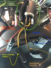
I have decided to use the female spade connectors for the factory tachometer wiring and change all the Speedhut wiring to matching spade connectors. Early V11 Sport wiring for (white face) Veglia shown above. For the 2nd gen V11 wiring with (black face) ITI, see Scud's Post#13:http://www.v11lemans.com/forums/index.php?showtopic=19038&p=204147 [ NOTE: I found it convenient to power the gauges from the factory red/black wire from Relay#2/ Fuse#5, but as Kiwi_Roy has posted repeatedly, the gauges re-initialize after cranking. Using the yellow (illumination) wires for gauge power bypasses this. ]
-
Yessir, I found a constant hot feed in my headlamp bucket I have wired from the battery (my junction block) through a 10 amp circuit breaker. This way I can route the (GPS )"Hot Start" wire without crossing the steering head. [ Note: this is not factory wiring to the headlamp, but a live power feed from the battery to relays I have added in the headlamp bucket for the headlight. ]
-
From the album: docc's sport
http://www.v11lemans.com/forums/index.php?showtopic=19038&p=220761 -
And the reset button instead of the twist knob:
-
Trading up to these for the cable assembly . . .
-

Rear brake binding and master cylinder Brembo PS11
docc replied to Jez2561's topic in Technical Topics
It's one of those systems that if each of the five or six things mentioned is a bit marginal, it all adds up to a significant problem.- 28 replies
-
- 1
-

-
- Brakes
- Rear brakes
- (and 2 more)
-
Rear brake binding and master cylinder Brembo PS11
docc replied to Jez2561's topic in Technical Topics
Plus, the pads slide on a single pin that rides in the road spray, especially if the plastic protective cap has gone missing. The pin gets awfully nasty, corroded, and can even develop grooves that can cause the pad to drag even if the piston retracts. Make sure the pin is clean, polished with something like 600 grit wet-dry paper, and lightly coated with silicone brake grease. The careful (nipple up) bleeding, overnight brake application, and thoroughly restoring the even piston motion are also all necessary, as well as fettling the activation at the master cylinder as have already been mentioned. -
Correct, Tail Light is on with the Ignition Switch; Brake Light on with either of the front or rear Brake Light Switch. Cdogger, could you restate what the filaments do 1) ignition on, 2) front brake applied, 3) rear brake applied?
-
Depending on how it has been stored, it may be worth closely inspecting the wiring for rodent damage.
-
Gearbox plug came today complete with O-ring and thread protector. Nice polished finish (better than pictured in the part reference). Just under $10US shipped from Illinois, USA. https://www.zoro.com/parker-hollow-hex-plug-m16-x-15-metric-vsti16x15edcf/i/G5007764/?q=G5007764 Very tidy! Now to pull the tank and fish out the cable housing.
-
maybe I missed it but that's a dang nice replacement. About as close to the original that I've seen. I hate to ask if you already posted Docc but did you list the order options for this? It would be a great reference for the next guy wanting a replacement. I would want the exact same thing. So, I think I ticked every box and added every possible option. The final faces are the result of five proofs benefiting from a series of printed mock-ups I used to refine the design. Josh, and Goofman, and my son with the V7 café helped immensely through the design process. I'll post another summary when I get the wiring done . Not including the various fasteners and other materials for the mounting, the Speedhut cost made it to $559.90US.
-
I'm about finished with the mounting. I decided to retain the gauge "mount" cover (the black ABS "cups" that house the leading edge of the gauges as well as the wiring for the warning lights.) Because the Speedhut connections are more like audio equipment than what I would expect of reliable weatherproof motorcycle connections, I closed up all the mount/cover openings using trim plugs and polystyrene plate, affixed with JB Weld epoxy: I used the mounting for the warning light receptacle to reattach the mount /cover by chasing the sleeve threads and using it as a pattern to drill three new holes in the mount/cover for M4 x 50mm machine screws inserted from the front: The gauges themselves are located ("indexed") with three M5 set screws tapped through the ABS gauge cover, and a pair, each, of 3 1/8" ID x 1/8" round section Nitrile 70 durometer O-rings [ if I had more patience/time, I would have sourced rectangular section O-rings rather than the round section ]: Next, to divine the wiring in order to minimize the number of connections and excessive lengths of wire. Even with the shortened wires I specified, there is twenty-five feet of wire and seven connectors. (Without using the dimmer).
-
That's just beautiful: both the prose and the photo . . .
-
Back in the saddle! Again!
-
Not sure on your relay order, front to back?
-
Wow, Dale! What a looker!
-
Pretty sure all my Wants&Warrants in Arkansas have sunsetted . . .
-
This is one of those questions that, over time, prompted me to divine the "Decent Tune-up" from so many years of so many people working at sorting out these issues. It is a "baseline" that should be performed before changing cross-overs, adding "PC" devices, re-mapping, and the like. Is it the end-all and be-all and final word? Not at all. But it is a solid, well derived starting point. I didn't make it up, but assembled the procedure as a compendium that should be approachable by most owners with a computer, a volt meter and some gumption. Just add gumption!
-
I'm listening . . . I love this plan; could be the first *Spine Raid* outside of the "South'n" Spine Raid held on the TN/NC (USA) border since 2004.
-
She's likely wired just like an early V11 Sport. The last relay (rearmost) in the row is overburdened (coils, fuel pump, injectors). Can you hear the fuel pump prime when you cycle the Run Switch?
-
With the key on, do you get 12v at the power supply to the coil(s)? There are five relays under the seat?